Continue to Site

Eng-Tips is the largest engineering community on the Internet

Intelligent Work Forums for Engineering Professionals

  • Congratulations KootK on being selected by the Eng-Tips community for having the most helpful posts in the forums last week. Way to Go!

Flow stall after pipe drops down 9

Status
Not open for further replies.

markboc

Bioengineer
Sep 1, 2020
19
Hello,

we have the following problem: A heat exchanger (15 m) is fed by a pump (0 m). It is a pipe network where other heat exchangers on parallel pipes are located much lower. The pressure gauges read low to negative pressures right before and behind the heat exchanger. Throttling behind the heat exchanger seems to solve the problem. It is suspected that the flow stalls after the heighest point of that branch of the piping system. Nonetheless the flow rate through that branch is higher than through the branch that contains the other heat exchangers, located lower.
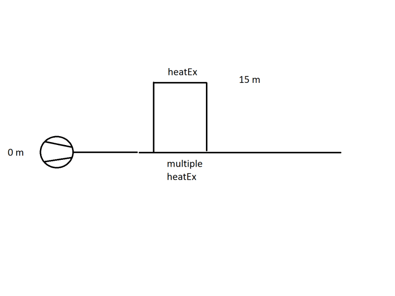
image_w5kpc4.png


1) Can anyone direct me to literature or suitable key words for google, to get more information on the problem of the flow stalling? We suspected because the flow experiences a free fall and accelerates the vacuum in the heat exchanger is created.

2) Another mitigation which was thought of: install a throttling valve behind the pump before the pipes branches in order to increase the pressure. The increased pressure should make sure that the 15 m heat exchanger is supplied with medium. My questions here are:
2.a) The pump head matches the pressure losses of the pipe network. If I install a throttling valve the pressure will rise, but only before the valve. The increase in pressure should match the pressure drop across the valve. So in my opinion it is not possible to control the pressure in the pipe network with this method.
2.b) I am correct in assessing that the pressure at branching point does need to be greather than 15 m + pressure losses across the pipe + pressure loss across the heat exchanger. I suspect this does not pose a problem as long as the pressure loss across the other path is high enough. This would lead me to think we can ensure proper operation by throttling in the branch where the 15 m heat exchanger is NOT located.

Basically I'm trying to determine at which points we can try to control the flow in a manner, where we have no negative presssure at 15 m.

I'd appreciate your input on the situation,

have a nice weekend!
 
Replies continue below

Recommended for you

I'll adress the other questions raised in depth tomorrow.

Just to clariy: There is no other flow control valve than V2. Currently V2 is a manual valve (flap?) and will be upgraded to an automatic rotary plug valve. Maybe this upgrade started the confusion that there maybe another flow control valve.

All other valves (existent d/s the Hxn right now and the maybe to be installed red one) should then control the flow ratio and foremost ensure that there is enough pressure at Hx1.

Thank you all for taking your time with me!
 
I disagree.

If you use V2 to control flow all that will happen is the flow will reduce and the pressure at P1 and P2 will fall further than they do at the moment. V2 is shown upstream of the HX's.

If you throttle V1 then what you're doing is increasing the pressure upstream by reducing the overall flow rate and forcing more flow through HX 2 & 3. This will raise the system pressure upstream of V1 and hence remove the boiling / partial vacuum at P1 & P2.

Only by raising the pressure at P1 and P2 to > 0 barg will this system have a chance of working properly. The easiest way to do that, IMHO, is to install a control valve anywhere on the common return leg downstream of all heat exchangers before it gets back to the tank. You probably want to control on flow at that valve.

Remember - More details = better answers
Also: If you get a response it's polite to respond to it.
 
LittleInch said:
If you use V2 to control flow all that will happen is the flow will reduce and the pressure at P1 and P2 will fall further than they do at the moment. V2 is shown upstream of the HX's.

What you say I belive is universally true only if the pump is held to a constant discharge pressure. Otherwise we do not have enough info to tell. We need pump and valve Cv info to be sure how the system will respond. When the flow to a pump is reduced, as you know, head generally increases, that amount depending on the pump curves dH/dQ. So that adds some amount of head into the system.

With the drop in flowrate, all friction losses decrease. That also "adds head", or rather subtracts less head from the system.

So, now, look at what happened when you throttled V2. Yes, you "added" some pressure loss to the system, but the question is how much loss did you add, or rather subtract from the system by doing that. If the throttling of V2 at a now reduced flow created more pressure loss than was added by the increasing pump head and by the lesser friction losses in pipes, yes, then PI1 and PI2 will decrease, but if you do not get a pressure drop across V2 greater than the absolute value of the sum of the pressure gain from pump head increasing and the effect of lesser friction losses, then PI1 and PI2 will increase. BUT, as I implied, the overall response is dictated by pump-pipe head "gains" vs the loss at V2. So, without knowing pump curve and valve Cv, we don't know which way the PIs will go. It could be either way. It could increase pressure at the PIs, if the pump curve is steep, but might not if the pump curve is flat. Since operating points for these relatively large flows are usually within the steep regions of pump curves and pipe friction is high, I choose to give the narrative of an increasing net system head, pump head increase and reduced pipe friction equaling a net gain, ie. greater than valve loss, with a small valve position change, but correct, I can't be sure until we look at curves. Obviously, if V2 is closed completely, PIs go to near 0 barA, but the pump also goes to deadhead max.

A valve downstream of all HX will have the same effect as upstream. It makes no difference where you put that additional pressure drop (as long as it is not on the branches). The sum of all dPs would remain the same, given the same pump head and same flow across the valves. My preference is to have pump control valves near the pump. Downstream location is a good place to control backpressure on the HXs and cascade flow. It would also have similar but possibly reduced effect at the pump, as long as cascading stopped. If cascading continued even in a small amount, no effect would be seen at the pump until cascading stopped and the line "tightened up".

Don't you agree? I'm (pretty) sure I can put it into my Stoner program and demonstrate, but I'd rather not have to do that. But I will, if you say so.

This may also be why the system appears difficult to control. Mark mentioned that throttling V1 seems to help at times, but too much, when the V1 pressure drop exceeds all other gains, then PIs drop fast and that starts damaging heaters with low pressures and cascade flows. Maybe..
 
What do you mean by cascade flow? I couldn't really find an explanation.

1503-44 said:
A valve downstream of all HX will have the same effect as upstream. It makes no difference where you put that additional pressure drop (as long as it is not on the branches).
This would mean V2 could be used to control the pressure in the system, I read from all the posts that this is not the case?
I get that you can still get increased pressure depending on the pump curve and cv. Did your statement refer to that case? It wouldn't work if the pressure loss across V2 is greater than the gain in pump head though. Otherwise I would think that a control valve downstream of the union would have a greater effect, since the pressure upstream is increased which would certainly help mitigate the issue of too low pressure at P1 / P2.
If we replace V2 we can choose the new valve . The one we currently looked at has cvs of 1500 m^3 / h.
This is an interesting point actually as it got over my head that you actually can get a higher pressure downstream by using a control valve directly after the pump, even if not in all cases.
Placement of a possible control valve to increase pressure at p1/p2 is my main concern. From what I gathered I thought we agreed that the position it currently has, V2, is not viable.

1503-44 said:
It would also have similar but possibly reduced effect at the pump, as long as cascading stopped. If cascading continued even in a small amount, no effect would be seen at the pump until cascading stopped and the line "tightened up".
May be the language barrier, but I did not get that.

LittleInch said:
So the real solution, In My Opinion (IMO), is to introduce a flow control valve to force the pump back into the correct location with a valve located down stream of all the HXs. This will cause the pressure upstream to increase. Then you can play with all the control valves on the HXs to get your required split in flow between your different HXs and ensure that P1 & P2 are both > 0 barg.
This would strike me as the best solution, too.

Thank you really for your help, this helps me a lot in understanding my problem!

I already added gathering information on the design specs of all Hx for next week.
 
Cascade flow occurs when pressure drops below the vapor pressure of the water corresponding to its temperature at any given point. Pressure is no longer sufficient to drive enough flow in the pipe to keep it full, so the volume of liquid flowing at that point drops, the pipe is no longer flowing full and water vapor pressure, now being higher than the pressure imposed on the surface of the liquid water itself, is liberated to fill the empty space created by the reduced liquid volume. When that happens on a downward sloping pipe, it is said to "cascade" down the slope, similar to the motion of a river waterfall or river with air above it. It is not like usual gravity driven flow in a river, or like flow of water through a half-full pipe in a sewer system, because the pressure on the water's surface in those situations is always atmospheric pressure of one barA, greater than the water's vapor pressure, unless the water is boiling. In this instance, pressure exerted on the water surface is less than its vapor pressure, even at low temperatures, so the water effectively boils at low temperature and water vapor is created; I think of it as "low temperature steam".

Yes, actually any valve closing in the system will tend to raise pump pressure, as long as the pump is running freely, i.e. is not flow or pressure controlled in some manner. We often don't initially think like that, because most of the time we usually want to have a good control of pump discharge pressure in long pipelines to protect downstream pipe and equipment, often owned by others in a completely foreign network, from a pumps very high deadhead (no flow head) pressure, but in some more limited systems like yours (actually a loop back to itself), it is OK to let pump pressure float, as long as pipe and heaters are designed for that max pressure.

The control valve can technically have the same effect on the pump if it is placed anywhere that is not on the heater branches themselves, although it is more intuitive for us to see how PI1 pressure is directly affected by the increasing backpressure that would result from a valve placed immediately downstream of the last junction. Actually closing a valve placed on either heater branch will tend to raise upstream pressure too, but that effect will be mitigated, as that increased pressure will be immediately dissipated somewhat by forcing more flow down the other branch.

The cascading, or cavitation would continue until system pressure increased above vapor pressure and the pipe starts flowing full once again. That is because anywhere the pipe is not flowing full, the pressure at all of those points will always be equal to vapor pressure. In that regard, partially closing a downstream valve, but not enough to get pressure back above vapor pressure at the cascading point, will not stop water vapor from filling the still partially filled pipe. Pressure there still remains equal to vapor pressure ... and all pressures upstream of that place never "feel any need" to increase. They just see the same old constant downstream pressure, the vapor pressure, so they are all happy to just keep on doing whatever they were doing before tou tightened up on that valve. Once the cascading segment starts flowing full again, the pressure goes higher than vapor pressure and the pressure is free to climb higher. Then it starts transmitting that increasing backpressure all the way upstream again, because the pressure "discontinuity", caused by the never changing vapor pressure, has disappeared. Now increasing backpressures are free to travel all the way back upstream to the pump.

Placing the control valve downstream of all heaters is good, because it is easy to see how increasing backpressure there will cause all upstream pressures to increase and additionally it will reduce flow from the pump. That is what you want to do. However you must make sure that the heaters and all upstream pipe and equipment, instruments, everything, is designed for the pump's deadhead pressure; the maximum pressure that the pump can produce. If you control with V2, then you could keep the pump's deadhead pressure from reaching the heaters with a maximum pressure set for V2's outlet at a pressure lower than deadhead, if you needed to do that, if for some reason like the heaters have a lesser design pressure than pump's max. Either one could work, as long as max design pressures "harmonize". If a downstream control valve closes and pump does not stop instantly, you will get max pump discharge pressure at all points upstream of that valve.

Don't overlook finding the pump curve, or at least a known max possible discharge pressure, and the Cv coefficients of the valves. If you can find the Cv of the heaters, that would also help. If not some idea of a known pressure drop for their design flow rates.

By the way. If EN is your second language, you must be damn good at your first. If you don't mind my asking, what language would that be? If you prefer to keep that secret, no worries. I'm just a curious sort of guy.
 
Possible Control Option

It also occurs to me this morning, thinking about control options, that you could install that downstream control valve (PCV3) with its input pressure from PI2. Configure it to maintain PI2 at some set pressure > vapor pressure. That would stop cascade flow. You could also control pump flow by using V1 to a great extent. As long as PI2 is >= PCV3's set pressure, V1 would actively control the system, as PCV3 would remain fully open. If you tried to increase system flow by opening V2 more, the pump's output pressure would go lower and friction losses everywhere increase, all downstream pressures would tend to reduce. If PI2 tried to drop below PCV3's set pressure, then PCV3 would begin closing to keep PI2's pressure above its set pressure and thereby not allow cascade flow to start. PCV3 would then effectively take active control of system and opening V2 further would not produce any additional flow. I have used that control strategy on many pipelines that had steep slopes coming down from mountains just before reaching an export terminal at sea level. Without a PCV3 type control of backpressure, the flow coming down the slope would have tried to increase indefinitely, causing partially full pipe, vacuum/vapor pressures and cascade flow.

More About Cascade Flow

Flow down a sloping pipe, or down a vertical pipe will occur by upstream pipe pressure and by gravity. Flow down a hill can continue without pump pressure. Gravity takes over. For any given pipe slope and pipe diameter, there is a critical flow rate. It is the flow rate that has a frictional head loss exactly equal to the head gained by the fluid moving downhill. If flow is below critical flow rate for that slope, friction is lower than gravitational energy gained, therefore the liquid's velocity can increase. When velocity increases, Bernoilli says pressure reduces (at least until vapor pressure is reached). You can increase flow to the critical flow rate without adding pump pressure.

Conversely, if actual flow is greater than the critical flow rate, then friction loss is greater than that gained by gravity elevation drop and velocity must decrease. Bernoulli says when velocity decreases, then pressure increase, so flow tries to decrease and no further flow rate can be attained on that slope without adding pump pressure.

 
Another possible means of control.

Instead of installing additional valves, it may be possible to get control of low pressure in HX1, by using V1 as a control valve. Configure V1's pressure controller to act like PCV3 above. That would allow you to keep HX1 pressures higher than vapor pressure, but it would not control cascade flow downstream in that leg. If PI2 decreased, V1 would begin to close, raising pressure. Backpressure would build towards upstream, lowering flow in the HX1 branch. Higher pressure reaching the junction would divert the flow previously going to HX1 to go into the HXn leg and some amount of backpressure would eventually reach the pump, thereby tending to reduce system flow. A new flow pattern would result, a lesser flow to HX1 and probably a slightly lesser flow to the HXns. But knowing exactly how much the flows redistributed themselves, depending on the pump curve and how much pressure drop each leg has after the new flows stabilise. I think that may have been what the original designers intended by locating V1 where it is. It allows some control of system flow rate as well as some proportioning of flow between heater legs. A good analysis can tell how well it could work over various V1 positions. But this method will not control cascading, so that must not reach severe levels.

The same strategy could also be used in combination with a new PCV3 to try to achieve better control of flow proportioning going into one HX leg or the other while giving you control of the cascade effect.

At this point, you now probably have far too much to think about.

 
This is a common situation and Latexman is correct. The only way to fix it is to break the vacuum downstream from V1. In fact, I would not even go as "high tech" as a vacuum breaker. I have built several similar plants over the years and they all included a simple vent downstream of V1.

You currently have sub-atmospheric pressure at V1 and there is still enough pressure to get the water back to the tank. So raising the pressure to 0 gauge will only improve the situation.

You can be fairly certain that the damage to hx1 is due to cavitation.

It is important to prevent air being sucked down the vent and causing 2-phase problems further downstream (as already mentioned by others). The downleg from point A to point B must be made self-venting, which would be 600 mm for a flow of 500 m3/h. [Edit]Only the section from point A down to the 8m level needs to be this larger diameter.[/Edit]

Once these changes have been made the flows through the two branches can be balanced by setting V1 and the red valve. Many years of experience have shown me that this is the simplest, most reliable and easiest to operate solution.

Pump_Circuit2_ifln5v.gif


Katmar Software - AioFlo Pipe Hydraulics

"An undefined problem has an infinite number of solutions"
 
I feel that flow balancing can easily be done if required by introducing throttling valves/orifices in different HX branches.

Important factor is to prevent possibility of vacuum condition in pipeline. This may disturb the flow by cavitation as well as release of air at low pressure.

The loop is similar to power plant auxiliary cooling circuit where a number of auxiliary coolers are cooled by closed circuit water, the same water is cooled by CCCW coolers. A number of pumps supply water in closed loop similar to here.

The difference here is that we provide an expansion tank connected to pump suction at about 15-20 m elevation (needs calculation) . This tank in addition to providing pressure all over the circuit to prevent any vacuum conditions and also provide for thermal expansion volume for water.

The 8 m level in suction tank may be too low. It will be worthwhile to think of a small expansion tank at a higher level. This is possible if there is a margin available in design pressure.

Caution: If such a tank, the operating pressures of piping and equipment will increase. The design pressure of the system is to be checked.

 
Katmar,

www.valmatic.com/products/air-valves/vacuum- said:
breakerA Vacuum Breaker is mounted at critical pipeline high points, penstocks, or tanks and allows for rapid inflow of atmospheric air to reduce vacuum conditions in piping systems.

katmar said:
It is important to prevent air being sucked down the vent and causing 2-phase problems further downstream (as already mentioned by others). The downleg from point A to point B must be made self-venting, which would be 600 mm for a flow of 500 m3/h. [Edit]Only the section from point A down to the 8m level needs to be this larger diameter.

If it is important to prevent air being sucked down the vent, why have a vent and thus give air an opportunity to flow into the vent? Furthermore, correct me if I am wrong, if a reduced flow to HX1 is asked for, pressure could rise at the vent above atmospheric and start ejecting water from the pipe through the vent to atmosphere. Is it not so?

Personally I would only consider adding a vacuum breaker to any pipe only if the pipe has such thin walls that it could collapse under vacuum conditions, when atmospheric pressure is greater than pipe's internal pressure. Cascade flow can be easily tolerated at low levels, so I have yet to see the need for vacuum breaker valves or vents.
 
Goutam, introduction of multiple valves in each leg usually only serves to increase pressure in the system. Only one valve will be actively controlling anything. Closing any other valve slightly more only tends to increase pressure everywhere upstream and reduce it downstream, just as would closing the original valve. Any time you opened one valve more, you would have to start closing the other to maintain a constant system flow. The secondary valve closing would only divert flow from it to the other leg, which can usually be done simply by opening the original valve a little more anyway. At least if the valve is sized properly to do so. Multiple valves in this situations add probable unnecessary complexity and most likely will not give any real additional control over flow to the heater legs than what one valve is providing already. Multiple valves are often a sign of trying to over-control the system, unless there are 3 or more branches going to parallel heaters. IMO, you can usually do with 0 valves with no branches, 1 valve with 2 branches, 2 valves with 3 branches, etc. N-1 valves usually can be made to work, because tou can control the branch with no valve using the pump curve. IMO.

Pressures below vapor pressure in pipe is not always such a great problem that it needs to always be avoided.
 
Mark, please try to get pipe diameters, lengths and elevations. I think someone will want me to prove what I say. Actually I would be OK with that, but I'll need good info to do it.

 
This is a simple problem. You either should have a return leg from each heat exchanger back to the storage tank or have a separate pump on each heat exchanger loop.
 
@1503-44 The fact that the OP has observed pressures below atmospheric confirms that there is a vacuum in the downleg (marked A-B in the sketch) and this means that somewhere in the downleg there is a liquid-vapor interface. Having a vacuum, and even worse a variable vacuum, plays havoc with the plant - both in terms of operability and physical damage. Having a vent (or a vacuum breaker) allows air into the pipe and stops the pressure fluctuations in the vapor space.

However, there will be times when the flow rate changes and the liquid-vapor interface level rises. This would mean that either you accept the air being compressed or you vent it. I much prefer the vent option and maintaining a constant pressure downstream of V1. I know that you can get vacuum breakers that also vent over-pressures, but these devices need maintenance and sitting at the top of the plant where nobody sees them can mean that they get neglected. A simple vent with a 180 degree bend is cheaper and better.

The first time I saw an installation like this I also expected water to spray out at some point. In the 25 years the plant ran it never happened. If the vent is about 2m high and the piping hydraulics are reasonable it just won't happen.

Katmar Software - AioFlo Pipe Hydraulics

"An undefined problem has an infinite number of solutions"
 
@bimr That might make it easier to balance the flows through the branches, but it will not eliminate the vacuum problem. The vent I have described above is the usual way to do it - and it works so well that people are not even aware that there might have been a problem.

Katmar Software - AioFlo Pipe Hydraulics

"An undefined problem has an infinite number of solutions"
 
@1503-44
It is usually done in power plant aux cooling circuit. We provide globe valve/orifice at each branch to balance flows. You may be right in saying that one has to manipulate all the valves in all the branches to get the right balance of flows.

Engineers, think what we have done to the environment !
 
Thanks for answering my questions guys,

Goutam I agree. At Enron we did put valves on all branch lines. After 5, or 6 branches, one more valve didn't add much additional cost and sometimes having a little extra redundancy does not hurt.

Katmar, since I never do that with thick pipe walls, I'll take your word that it worked, but I think I would still not do that as long as my pipe wall was thick enough to handle vacuum and I would carefully study flow reduction and pressure rise situations, as during system start ups and shut downs. I have used a vacuum breaker on one large diameter, thin walled water supply pipeline, but only once. Otherwise I specified pipe walls that were able to tolerate vacuum.
 
When water in closed pipe is drained, the flow is almost always chaotic. Why? The pressure goes from - to + to - to +, glug, glug, glug, right? The dynamics are terrible. Vibrations and cavitation can result. That is why we always open a high vent, to introduce air for displacement and to get a constant (atmospheric) pressure, then the dynamics stop and flow is smooth.

The HX1 pipe is somewhat similar, right? The water falling down the 15 m is pulling the flow along, like a drain. OP said, "The pressure indicators PI 1 and PI 2 indicate negative pressures and hx1 is often damaged." Emphasis on often is mine. So, open a vent. The dynamics will stop. OP will have to learn anew how to balance all the HXs, but they will no longer be fighting the dynamics.

Good Luck,
Latexman
 
The problem is that the pressure is simply too low at HX1. Why is it operating at such low pressures. IMO, the system lacks sufficient pressure. The pump should have been supplied with more head to avoid that problem entirely. Why even take a chance on doing all the damage that is actually happening with that kind of design. If I had a choice, I would simply keep it always running well above vapor pressure... with increased and a controlled backpressure at all flow rates guaranteed. If that cannot be guaranteed at all flow rates from 0 to the max required with the present configuration, personally I would prefer to install a backpressure control valve that could be guaranteed to do exactly that, but no harm in looking at other potential solutions.

Way Forward

This system should first be analyzed to see if it can be properly operated with its present configuration and at the latest flow rate requirements.
Determine what any limitations to flow rate may be necessary to operate within other limitations.
Decide if any flow rate limitations are acceptable to meet current needs.
If not, then attempt to meet current flow rate requirements by making the minimum number of changes to the current configuration and without introducing any unnecessary complexities.
Determine what all the various options are and what the limitations may be, if any, for each option.
Include analysis of start up, ramping, operating ranges and shut down cases.
Select from the options that allow sufficient operating range, flexibility, ease of control and equipment safety and protection from cavitation, if that is indeed necessary.
Evaluate the cost effectiveness of each technically acceptable alternative.
Make final selection.

 
38 posts and a number of options.

The thing for me looking back at this is that there is something which just doesn't look right.

Working backwards from the tank, there is an inlet into the tank apprently at 8m, so this is a fixed back pressure.
There is then about 2-300m of pipe PLUS another HX not shown which is actually the chiller HX - " I completely forgot that. Yes somewhere d/s of the union point is another heat exchanger to actually take away the heat." So we have maybe another 8-10m frictional losses and losses accross the chiller HX.

So that gets us to approx 15m+ head at PI2. There must be losses across HX1 so PI1 should be > 15m and hence above atmospheric pressure.

The data given on the sketch shows 3.5 barg, so 35m D/S of the first HX. Even allowing the additional height of 15m, 20m head loss in pipework between that point and PI1?? Doesn't make sense.

I get what Katmar is saying and it will work if the pressure D/S Hx1 doesn't rise above 15m head.

SO I don't think we have the complete picture and it may take some time for anyone to figure this system out, but as I see it at the moment there are some discrepancies in what information we have.


Remember - More details = better answers
Also: If you get a response it's polite to respond to it.
 
Status
Not open for further replies.

Part and Inventory Search

Sponsor