Eng-Tips is the largest engineering community on the Internet

Intelligent Work Forums for Engineering Professionals

Fury 325 Rollercoaster cracking 15

Status
Not open for further replies.
Replies continue below

Recommended for you

Official Statement released today by Carowinds:

Carowinds_Statement_20230706_i5yuwj.jpg
 
They must be struggling to find an acceptable repair, and the butt-ugly temporary splice plates were just too noticeable. Better to hide the crack while they figure out what to do.

I'd like to know how the failed joint was originally made. I'm guessing the vertical pipe was notched to let the angled pipe fit in neatly for a better appearance.

I can't visualise any repair that isn't going to look ugly, so I'm anxious to see what they come up with.

UPDATE: Well, they couldn't come up with a repair either. I think replacing the entire column is the best solution. I wonder what changes if any they'll make to the design.
 
Resqcapt said:
Since this ride has been in operation for about 8 years, how likely is it that the root cause is a design flaw?

Design is likely a factor. The outward thrust is fairly substantial, and it was hammering away at the tip of the weld hundreds of times a day.
 
These complex joints do not lend themselves to simple analysis. This joint is obviously capable of transmitting a significant moment load through a complex geometry.

I one time had a similarly complex situation arise with a steam piping anchor failure - a 10 inch elbow having an 8 inch unpressurized pipe welded to it's backside (connected to an anchor plate). After about 1 year in service a crack developed along this weld, through the elbow which was acting as the pressure boundary.

We sent the geometry to an FEA modeler this was about 1989, so FEA was not all that common. The final answer was that the weld connection between the "cold" support pipe and the hot elbow was sufficiently constrained that the stress in the weld developed from temperature difference exceeded the material yield strength. This is despite the pipe passing code stress calculations for overall design.

Details matter!
 
Wonder if they're chalking this up to a defect or if the new column will feature some heavier members or different joint geometry/reinforcing.
 
Coaster_ryvwpf.png


That coaster is full of those kinds of connections. If I were B&M I'd be scrambling to understand the "why" before I got into a FIU bridge FIGG type situation where you THINK you know but you really don't.
 
It’s very complex. I wonder how they design for the thermal expansion/contraction, fitup
tolerances, and incidental support settlement?
 
It's certainly overconstrained so there are a lot of places where internal loads could develop and not get noticed.

For example - those supports are extremely rigid perpendicular to the track and all cooperate to take loads parallel to the track. So what happens as the track expands and contracts from the sunshine? All the give is in that tiny outcrop at the top of the supports.

In this case it may be that this fracture reduced the loads elsewhere.

I noted in the large bridge beam failure that it happened after a change in fixity at the ends of the bridge, increasing the tension loads and producing a similar fracture that also went unnoticed by the team of inspectors.

Please - inspectors - take photos so they can be overlaid year over year to photographically compare rather than supposing you will notice when sweat is dripping and the inspection bucket is bobbing. Go telephoto to get less distortion. Photos also let a second party do the comparison, a party that won't "know what they are looking at" and fill in the blanks on what they assume is there.
 
I wonder if this was one of those situations where a proven detail gets pushed a little further and a little further with each implementation until, one day, it is no longer sufficient.

The problem with sloppy work is that the supply FAR EXCEEDS the demand
 
Given that <sarcasm> Carowinds' comprehensive safety protocols detected the crack and responded immediately to shut down the ride </sarcasm> an actual disaster was prevented.

Therefore it looks like Carowinds and Bolliger & Mabillard intend to move forward and treat this as a maintenance repair. As such, there will likely be no comprehensive independent investigation nor any public disclosure of what actually caused the failure.

So, it's up to us and the rest of the internet to speculate and analyze.

Anybody here a NC or SC resident and willing to write a strongly worded email to the state demanding accountability?
 
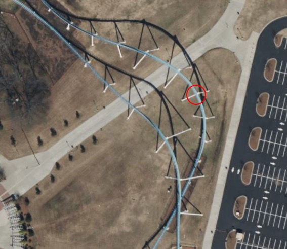
Not that it matters now, but I've come up with a way to repair the broken support that is reasonably easy and will look exactly like the original build.

1. Using whatever means are necessary, pull the broken parts back into alignment, V out the joint, and weld it up.
2. Cut a hole in the plate on top of the column to the inside diameter of the pipe. Fashion a sleeve that can be lowered into the pipe with the lower end shaped to avoid any intruding obstacles. Try to get as much circumferential coverage as possible above and below the joint. The sleeve might need to be open on the side toward the rail or in two pieces.
3. Drill a suitable pattern of holes in the pipe above and below the joint so the sleeve can be plug-welded to the pipe.
4. Do all the usual cleaning, grinding, and clamping to get the sleeve fitting as tight as possible inside the pipe, and do the plug welding to secure it in place.
5. Weld the piece removed from the top plate back in place, grind everything smooth, and repaint the area.

That'll be as strong or stronger than the original, and it could be done in a lot less time than fabbing and shipping a new column from Italy.

Of course, you'd need a work platform, a protective tent around the work area, and some portable weld inspection stuff, but that's all doable.
 
Status
Not open for further replies.
Back
Top