Eng-Tips is the largest engineering community on the Internet

Intelligent Work Forums for Engineering Professionals

General Notes Contents and how it relates to ASME Y14 2

Status
Not open for further replies.

Harry Houdini

Aerospace
Jan 22, 2021
18
0
0
US
Good afternoon fellow engineers. I had a quick question regarding the contents of this drawings GENERAL NOTES. I want to know if anything that I defined in the general drawing notes directly violates anything withing ASME Y14 Standards.

[ul]
[li]Every part will be sent to a manufacturer with a STEP file and a PDF of the technical drawing.[/li]
[li]We are using an ALL OVER profile tolerance with datums.[/li]
[li]Every drawing will have datums on it.[/li]
[li]Drawing may or may not be completely fully defined by dimensions on the sheet[/li]
[li]When dimensions are not shown, any missing dimension or value should be grabbed from the CAD Model[/li]
[li]If a value is pulled from the model, then it should be considered BASIC because I want the value to have a tolerance based off of the profile[/li]
[li]We currently have an issue where a decent amount of drawings are note fully defined by drawing dimensions (which manufacturers are okay with) but we have a machinist who does everything by hand, so he requires fully dimensioned drawings. This led to the reference dimension section about how they are BASIC. I am super uneasy about this and I think it may clash with ASME.[/li]
[/ul]

Drawing_Notes_oga8o4.png
 
Replies continue below

Recommended for you

When you apply profile all-over the true profile is the entire part, defined by basic geometry (as queried from the cad model in your case). In that case, a datum reference frame is redundant. Maybe it's not really all-over?

Also, I wouldn't call what you refer to a "partially defined" drawing. I think Reduced dimensioning/minimally dimensioned drawing/model based definition are better terms.
 
"When you apply profile all-over the true profile is the entire part, defined by basic geometry (as queried from the cad model in your case). In that case, a datum reference frame is redundant. Maybe it's not really all-over?"
[ul]
[li]So we call out an all over profile tolerance so that any dimension not on the drawing will be pulled from the CAD model. I was told that if you are trying to do the entire geometry of the part you need to have ALL OVER to specify that its the entire geometry. With that said, I was also told that a profile tolerance without DATUMS (regardless if its ALL OVER, ALL AROUND) will not be technically correct / accurate without DATUMS associated with it. Now when you say DATUM REFERNCE FRAME, you are talking about the entire profile tolerance block, not just the DATUMS?[/li]
[/ul]

"Also, I wouldn't call what you refer to a "partially defined" drawing. I think Reduced dimensioning/minimally dimensioned drawing/model based definition are better terms."
[ul]
[li]I think you may be right. We put this on all of our drawings so would it be incorrect if I had it on a part that was fully defined by the drawing? A lot of our drawings are not fully dimensioned but Manufacturing and QA would prefer if I could find a way to keep the notes (WHEN APPLICABLE)on there so we don't have issues down the road. [/li]
[/ul]
 
The DRF (in this case [A|B|C]) is not redundant, though it could leave some tolerance unable to be used. At the expense of that loss the inspector doesn't have to search for a location and orientation of the part geometry such that it can be confirmed to meet the requirement which also cuts down on arguments with manufacturing about repeatability. Each individual surface can be independently inspected for conformance rather than being forced to do so among all of them simultaneously.
 
Harry Houdini said:
So we call out an all over profile tolerance so that any dimension not on the drawing will be pulled from the CAD model.

Note D. in your embedded image specifies that dimensions not on the drawing shall be queried from the model. It's not profile all-over that invokes this.

Harry Houdini said:
I was told that if you are trying to do the entire geometry of the part you need to have ALL OVER to specify that its the entire geometry.

The typical and recommended practice when a general profile tolerance is specified with references to datum features, is that the datum features are first qualified by geometric tolerances that also relate them to each other; the primary datum feature is qualified by a form tolerance, the secondary by orientation and sometimes location to the primary, and the tertiary by orientation and sometimes location to the primary and secondary. Then the general profile tolerance applies to some/most/all other features, controlling them relative to the datums.

Harry Houdini said:
With that said, I was also told that a profile tolerance without DATUMS (regardless if its ALL OVER, ALL AROUND) will not be technically correct / accurate without DATUMS associated with it

Profile without datums, when applied to multiple surfaces by a single feature control frame controls the form and the size (if applicable) of the features, and the location and orientation of these features relative to each other. If all-over is applied, the entire part is controlled that way. Referencing datum features in conjunction with all over will make only half the tolerance zone available for the datum features, but other than that it won't do anything that profile all-over without datum references doesn't do.

Harry Houdini said:
Now when you say DATUM REFERNCE FRAME, you are talking about the entire profile tolerance block, not just the DATUMS?

I am talking about the 3 perpendicular planes (forming a coordinate axis system) called the Datum Reference Frame and the things that lead to its establishment; datum features and datums. All are unnecessary when the profile applies all-over. See below.

20210123_230447_xlkp9j.jpg
 
This is all super helpful and I appreciate everyone taking time out of their day to help me! THANK YOU!

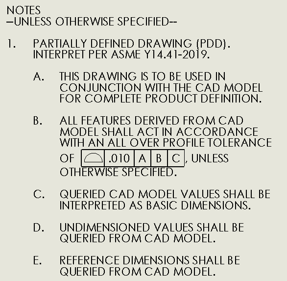
1. PARTIALLY DEFINED DRAWING (PDD). INTERPRET PER ASME Y14.41-2019.
[ul]
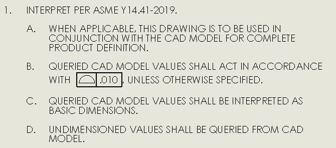
[li]So we have discussed that saying PARTIALLY DEFINED DRAWING is technically the wrong terminology and should be something like MINIMALLY DIMENSIONED DRAWING or REDUCED DIMENSIONED DRAWING.[/li]
[li]Also I would like to put something like, [/li]
[/ul]

A. THIS DRAWING IS TO BE USED IN CONJUNCTION WITH THE CAD MODEL FOR COMPLETE PRODUCT DEFINITION.
[ul]
[li]No issues with this?[/li]
[/ul]

B. ALL FEATURES DERIVED FROM CAD MODEL SHALL ACT IN ACCORDANCE AN AN ALL OVER PROFILE TOLERANCE OF [.010 ABC]. UNLESS OTHERWISE SPECIFIED.
[ul]
[li]It looks like the general consensus is that saying ALL OVER is correct, but it would be better if I didn't use DATUMs in the feature control frame.[/li]
[/ul]

C. QUERIED CAD MODEL VALUES SHALL BE INTERPRETED AS BASIC DIMENSIONS.
[ul]
[li]The idea was, when there is a scenario where there are missing dimensions (dimensions deliberately being left out by the designer) values would have to be pulled from the CAD Model as a result. If that happens, all values pulled would be considered basic. If they are basic then they must be associated with some sort of GD&T. Thus all the values pulled form the cad shall conform with the specified General Profile Tolerance. is this a gross misunderstanding of how I am interpreting this?[/li]
[/ul]
D. UNDIMENSIONED VALUES SHALL BE QUERIED FROM THE CAD MODEL.
[ul]
[li]see explanation above.[/li]
[/ul]
E. REFERENCE DIMENSIONS SHALL BE QUERIED FROM CAD MODEL.
[ul]
[li]The only reason this is here is because we have a couple scenarios where the machinist who is making the parts for us is unable to use the cad file, he machines it "by hand". So when we give him a drawing that is not fully dimensioned, he cannot machine the part. In an effort to fix this, we dimension all other features but we make them all reference dimensions. This way our special machinist can still make the parts, but our other manufacturing people can disregard these reference dimensions and use the cad model / profile tolerance.[/li]
[li]My general understanding is that we are using Reference Dimensions inappropriately / not to their intended use. [/li]
[/ul]
 
It is better to not use datum features, but this can cause inspection to be more expensive and take more time.

If the parts are likely to be fixtured for manufacture then the datum features can be used for tooling.

If money is no object, then don't use them.
 
Harry Houdini,
If physical fixturing (datum feature simulators) is likely to be used for inspection, then the better solution is to apply geometrical tolerances on the datum features separately and specify the general profile tolerance without all-over. Often inspecting the datum features with reference to themselves is not very practical with (physical) datum feature simulators.

If a physical fixture is not expected to be used and the entire part is likely to be scanned and analyzed digitally by the optical/laser inspection software, referencing datum features in conjunction with all over will not cut you any costs. On the contrary, some cost will be added by the need to simulate the datums and define the tolerance zone relative to them rather than performing a best-fit procedure, and also by the reduced tolerance zone available for the features you assign as datum features.

As for the reference dimensions you want to be interpreted as basic, just show them on the drawing as basic.
As long as the basic dimensions on the drawing are in agreement with the CAD model, why there should be an issue?

I see no issues with the rest.

 
Software can simulate datums at no additional cost.

Spending money on a laser scanning CMM is an example of the extra cost I was referring to. Sure, once the big bucks have been spent a lot of things have little cost impact, but the up-front cost is still a cost.
 
3DDave said:
Software can simulate datums at no additional cost.

What about the time it takes for the inspection programmer to establish the DRF and relate the scanned part to the true geometric counterparts (theoretical datum feature simulators) according to the datum precedence order?
Even if it's negligible, there is no added value in doing it for an all-over profile requirement, when compared to a best-fit that could be performed in the case of no datums. That is unless someone wishes to provide half the tolerance (for an equal bilateral profile tolerance) for the datum features variation than for everything else on the part and that's how he chooses to achieve it - which seems unlikely.

Anyway, as I mentioned a tighter tolerance for the datum features as an outcome of such practice clearly can make the part more costly.

3DDave said:
Spending money on a laser scanning CMM is an example of the extra cost I was referring to

The OP already indicated that such equipment is available in the company and provides cost-effectivity:

Harry Houdini said:
we can sometimes use optical / laser inspections that save us a ton of time
 
"can sometimes" means not always.

It was only mentioned -after- I talked about the cost. I hope that clarifies that reading comments out of order to score debating points is a weak way to go.
 
For more information regarding REFERENCE DIMENSIONS.

There is a very specific reason we do not put BASIC dimensions on the drawing when we are referring to the general profile tolerance. I understand that normally if you are trying to reference the general profile tolerance you would want to have the dimensions as BASIC, but we have additional drawing notes for FIRST ARTICLE INSPECTIONS that required a FAI for every dimension on the drawing. So if there are a lot of dimensions we do not care about that can be picked up by the profile tolerance (which is loser than the dimensioned features) then we weren't going to have them inspected those dimensions. If they are basic on the drawing, then they would have to inspect them. Thats why we were making them reference so they could be disregarded by the inspector.
 
Just to be clear, because I am a little confused...

General Profile Tolerance Options
[ul]
[li]ALL OVER [PT of .010 ABC][/li]
[li]ALL OVER [PT of .010][/li]
[li][PT of .010 ABC][/li]
[li][PT of .010][/li]
[/ul]

ALL OVER Usage
[ul]
[li]it was to my knowledge that an ALL OVER callout was mandatory when referring to the entire part. I am not sure how I would call out a profile tolerance across the whole part without using that syntax. I am reading that it is not preferred to use ALL OVER because you are applying the general profile tolerance to the datum features as well? It sounds like it would be better to remove the ALL OVER callout so that pretty much everything but the DATUM features are potentially picked up by the general tolerance. The DATUM features themselves should be tolerances on the drawing. Does what I said make sense?[/li]
[/ul]

ABC Usage in General Profile Tolerance
[ul]
[li]Using DATUMS in conjunction with ALL OVER, from what I understand, is not preferred for the reasons stated in my previous bullet.[/li]
[li]Using DATUMS would be preferred if I am going to physically orientate the part before inspection?[/li]
[li]Using DATUMS would be preferred if the machinist uses them as he machining the part for inspections.[/li]
[li]Using DATUMS could be a cost problem only if scanning method is not being used as scanning inspections can simulate DATUM features with no additional cost.[/li]
[li]Removing DATUMS would be preferred if I am scanning the part as a whole so BEST-FIT practices could be used? Because you don't want to use BEST-FIT and trying to relate DATUMs to themselves. [/li]
[/ul]

IS ANYTHING I SAID ABOVE INCORRECT?
 
I think you need a class about the subject to understand the effects of the callouts rather than blindly adding notes to the drawing. Perhaps a conversation with your QA department members and members of your manufacturing engineering staff. They are the ones you are attempting to obligate with these rules.

I'll add that having no concerns about how parts are produced and what affect it has on other segments of the company is called "Throw it over the wall." Normally that is frowned upon, but some people think it's the best approach. It usually results in getting product out that doesn't work right because the people doing the throwing don't understand all the implications of what they have asked for leading to drawing-compliant, functionally deficient product. Look up Takata, for example.
 
Harry Houdini said:
I am reading that it is not preferred to use ALL OVER because you are applying the general profile tolerance to the datum features as well? It sounds like it would be better to remove the ALL OVER callout so that pretty much everything but the DATUM features are potentially picked up by the general tolerance. The DATUM features themselves should be tolerances on the drawing. Does what I said make sense?

Yes, that makes sense.
Also, a general profile tolerance is usually relatively loose and is applied to less critical features. Tighter tolerances on a minimally dimensioned drawing are applied to datum features and features critical for function, directly in the orthographic or axonometric views.

I agree with most of the bullets on "ABC Usage in General Profile Tolerance" except for these two:

"Using DATUMS would be preferred if the machinist uses them as he machining the part for inspections."

What the machinist does or does not do is not what drives the type of definition on the drawing. The primary support for using datums is functional considerations. Most of the time you want the part fixtured for inspection the same way it is assembled
when used, and the tolerance zones to be related to the datums simulated by the fixture acting similar to the mating part. That is in a nutshell how you take care of function. That is not to say that geometric tolerances without datum references are not useful. If one profile tolerance requirement all-over is all it takes to make the part functional, then datums are not a must.

"Using DATUMS could be a cost problem only if scanning method is not being used as scanning inspections can simulate DATUM features with no additional cost."

Datum simulation can often be performed with simple tools such as a surface plate, V-blocks, chucks, vises, etc. that do not require any special expenses. If you need to build a complex customized inspection fixture for a part then yes that might be costly and often advanced measurement machines, if available, can spare it. But I don't see a scenario where profile all-over with datum references is more cost-effective than just a conventional profile all-over without any datum references. Again - you should consider carefully if you need all-over or not. All-over puts your entire part within one single tolerance zone, regardless if you reference datums or not.

I still don't understand the bit about reference dimensions specified to be interpreted as basic in drawing notes instead of being shown as basic. Doesn't that note defeat whatever purpose is attempted to be achieved by showing the dimensions as reference?

 
Harry Houdini,
Yes, your latest version of the drawing notes looks good to me, for the most part.

One thing to note is since you do not use datum features, this time it does make sense to add "all-over" to make it clear that all tolerance zones for the different features are tied together and essentially form a pattern, that can also be looked at as a single continuous tolerance zone for the entire part. Otherwise, the tolerance zones can be disjointed (although some may tell you that profile without datums applied to multiple surfaces creates a simultaneous requirement, but that is not true).
 
Hi All,

As we can see from this discussion, the use of datum feature references in a general profile tolerance is a complicated issue. Specifying datum features will introduce both advantages and disadvantages, and what these are will be specific to the situation in several ways. There will be compromises between amount of manufacturing tolerance, complexity of the GD&T callouts and their interpretation, complexity of inspection equipment required, complexity of inspection calculations, and reproducibility of inspection results.

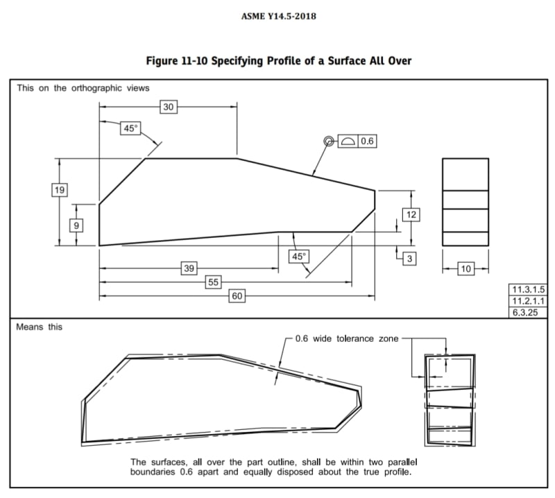
If the function of the part dictates that no feature takes precedence over the others, then the all-over profile tolerance with no datum features (as in Fig. 11-10 above) captures that function and allows the most tolerance. Specifying datum features will always make the specification more restrictive, because this will require the profile zone to be aligned to the part in a particular way. Whether or not this restriction makes the part more significantly more difficult or expensive to manufacture depends on the situation.

Evan Janeshewski

Axymetrix Quality Engineering Inc.
 
One thing to note is since you do not use datum features, this time it does make sense to add "all-over" to make it clear that all tolerance zones for the different features are tied together and essentially form a pattern, that can also be looked at as a single continuous tolerance zone for the entire part. Otherwise, the tolerance zones can be disjointed (although some may tell you that profile without datums applied to multiple surfaces creates a simultaneous requirement, but that is not true).

Just to be 100% clear, does this pose any issue if I am specifying DATUMs on every part. Does it still make sense to do an ALL OVER callout with a [general profile without DATUMs] even though I am specifying DATUMs on the part? Sorry if this has already been talked about!
 
Status
Not open for further replies.
Back
Top