Eng-Tips is the largest engineering community on the Internet

Intelligent Work Forums for Engineering Professionals

General Notes Contents and how it relates to ASME Y14 2

Status
Not open for further replies.

Harry Houdini

Aerospace
Jan 22, 2021
18
0
0
US
Good afternoon fellow engineers. I had a quick question regarding the contents of this drawings GENERAL NOTES. I want to know if anything that I defined in the general drawing notes directly violates anything withing ASME Y14 Standards.

[ul]
[li]Every part will be sent to a manufacturer with a STEP file and a PDF of the technical drawing.[/li]
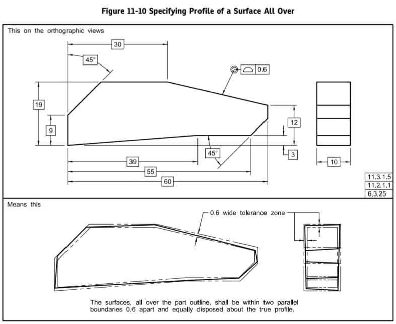
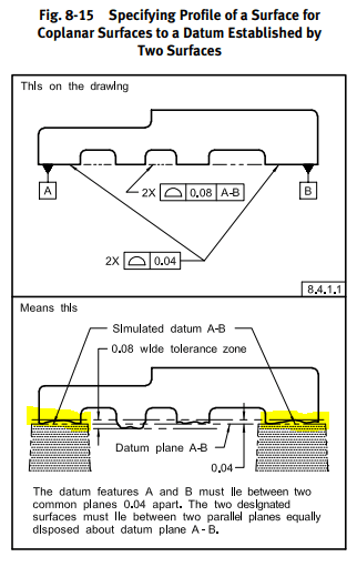
[li]We are using an ALL OVER profile tolerance with datums.[/li]
[li]Every drawing will have datums on it.[/li]
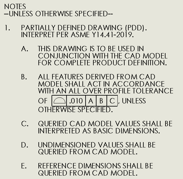
[li]Drawing may or may not be completely fully defined by dimensions on the sheet[/li]
[li]When dimensions are not shown, any missing dimension or value should be grabbed from the CAD Model[/li]
[li]If a value is pulled from the model, then it should be considered BASIC because I want the value to have a tolerance based off of the profile[/li]
[li]We currently have an issue where a decent amount of drawings are note fully defined by drawing dimensions (which manufacturers are okay with) but we have a machinist who does everything by hand, so he requires fully dimensioned drawings. This led to the reference dimension section about how they are BASIC. I am super uneasy about this and I think it may clash with ASME.[/li]
[/ul]


Drawing_Notes_oga8o4.png
 
Replies continue below

Recommended for you

Does it still make sense?

Perform the tolerance stackups and the stress analysis and discuss this with cost-estimating, manufacturing, inspection, and customers in order to decide if it makes sense.

Use the same analysis on multiple ways to describe the part to see what the outcome in terms of performance and schedule and cost will be. No one here can tell you absolutely that their answer is the best one for every possible case based on a default when there's no information about all the remaining factors.

Doing the work for your own parts and drawings is the only way to see if it makes sense.
 
We are a relatively small company and design is a little all over the place when it comes to inspection and manufacturing. I have been implementing standardization across a lot of different avenues in hopes force designers to use standardized methods. I understand that there is no real way to standardize general drawing notes to apply to every single scenario, but I am hoping I can do it for the majority of the parts we manufacture and inspect to keep overall design / quality up. I work at a company where if you look at 5 drawings each from a different person, they all look vastly different from one another.
 
Harry Houdini, you asked:
"Does it still make sense to do an ALL OVER callout with a [general profile without DATUMs] even though I am specifying DATUMs on the part?"

I assume you mean that you wish to specify the all-over tolerance without datums as a general tolerance in the notes, while there are datum features designated and geometrical tolerances that reference those datum features in the drawing views. Is that what you mean?
I would say that this is an unusual scheme but it is possible to do so if that truly captures your design intent.
Most of the time though, as I've mentioned before, one would want to reference the functional interface surfaces as datum features in the general tolerance requirement and NOT apply it all-over.

Anyway, here are my recommendations so far listed and hopefully clarified some more:

1. If you do not reference datums, as in your latest embedded image of the drawing notes, specify all-over to avoid disjointed tolerance zones.

2. If you prefer to specify all-over anyway and you are still not sure whether to reference datums or not, consider not specifying them as they will not provide you any added value - not even for inspection convenience. I will address this later.

3. If you prefer to reference datums anyway consider not specifying all-over and controlling the datum features separately on the drawing views.


Now to why datum references are redundant in conjunction with all-over:

Option a.
Consider a simple square prism with basic dimensions 5 X 5 X 5 mm.
If you tolerance it by profile all-over within 0.2 with reference to A, B, C where datum features A, B, C are 3 faces of the cube, the only way to inspect it is to simulate 3 perpendicular planes (datums) either physically by using inspection blocks or digitally by your CMM program, engage the part with the datum feature simulators (the inspection blocks) or the true geometric counterparts, establish your true profile and tolerance zone in a fixed spatial relationship with the datums, and check conformance and actual values for the profile requirement.
When the part is constrained to the simulated datums, each of the datum features will have only 0.1mm of tolerance available for variation (half the tolerance zone).

Option b.
Now consider that the profile is specified all-over without referencing datum features. This means that as far as the designer's requirement is concerned the tolerance zone for the entire part is not tied to anything. You have two possible ways to inspect this: either scan the whole part and perform a best fit procedure, or repeat the exact same process as for option 1 above. Even though per the drawing the tolerance zone is not constrained to anything other than the 5 X 5 X 5 true profile, it won't be wrong to support the part on the inspection blocks if inspecting 3 of the faces relative to the planar fixture surfaces that contact them is feasible and this method is more convenient or cost-effective. A part that passes the hard-gaging inspection process, would also be approved by the best-fit procedure.

On the other hand, if the datums are referenced in the profile all-over requirement, a part that passes the (inadequate for this case) best-fit inspection, would not necessarily pass the datum-constrained inspection. So if functionally the two options are adequate, Option a. may actually reject some good parts and cost the company some extra-money.

The above is not limited to square prisms.
You can extend this principle to parts of any shape and structure.
 
This makes complete sense!

My only question is about the following sentence:


If a cube has the "bottom" surface as DATUM A, why wouldn't it have a profile tolerance band of 0.2. Is this because its outer tolerance zone (the 0.1 tol zone larger than nominal) is constrained by fixturing so the tolerance band can only go into the part?
 
I guess what I mean is, if I specify DATUMS in the general tolerance, the profile tolerance is based off DATUMS, effecting where the true envelope will lie on the part? Meaning the envelope with be oriented via the DATUMS VS there being an envelope based of the nominal part (when the profile doesn't have DATUMs associated with it?

I guess what I am looking for is an image like this, comparing the use of DATUMs in the profile tolerance Feature Control Frame vs no datums in the Feature Control Frame.

Sorry if I am being difficult haha
image_2021-01-25_112916_rffgp4.png
 
Harry Houdini said:
If a cube has the "bottom" surface as DATUM A, why wouldn't it have a profile tolerance band of 0.2. Is this because its outer tolerance zone (the 0.1 tol zone larger than nominal) is constrained by fixturing so the tolerance band can only go into the part?

Yes, but that is not only a result of the physical fixturing. It is the result of how datum planes are defined to be established according to ASME Y14.5. A primary datum plane is a plane that contacts the datum feature at the three (at least) highest points of the surface. When you reference datums in the profile FCF in conjunction with all-over the true profile - which is located in the middle of the tolerance zone (for the default bilateral equally disposed profile tolerance), is coincident with the datums at the datum features. That way the true profile (and the middle of the tolerance zone is consequently coincident with the highest points of the datum feature's surface. So any variations of the datum features are only allowed into the material, relative to the true profile.

By the way, I forgot to mention that if you are going to specify a general all-over tolerance as a note while having datum features and tolerances referencing them in the views, you have to make sure that all geometrical tolerances in the views are tighter than the general tolerance. Everything in the views should be a refinement if the general tolerance is all-over.
 
YES THAT ALL MAKES SENSE. Wow that took awhile to finally understand haha. So with that said, it sounds like I definitely do not want to specify DATUMs in the general profile tolerance because there is a potential for parts to be flagged during inspection due to the fact that I made the General Profile Tolerance related to the DATUMs.


Regarding this. Yes we have the general profile tolerance at .010 and all of our other dimensions are +-.005 or tighter.

So... It would be in my best interest to:
[ul]
[li]have DATUMs in the drawing view.[/li]
[li]no DATUMs in the GENERAL PROFILE TOLERANCE located in the GENERAL DRAWING NOTES[/li]
[li]have an ALL OVER callout before the GENERAL PROFILE TOLERANCE to avoid disjointed tolerance zones[/li]
[/ul]
 
Harry Houdini, I would double check if you really need the requirement of specifying datums on every part. There might be cases where an all over general profile tolerance of .010" is sufficient for the functionality of the part. Also, something you might want to check is if any of your drawings have already have a space for general tolerances where you would typically see bilateral tolerances specific to dimensions of a certain number of decimal places. If so, you may consider omitting those and putting your all over general profile tolerance in that space.
 
We do have a tolerance block that has .XX and .XXX but this generally only relates to dimensions shown in the drawing view. I've been told that its generally good practice to have DATUMs in the drawing view for inspection.
 
Harry Houdini,

Your drawing should conform to ASME Y14.5[‑]2018. ASME Y14.41[‑]2019 is for interpreting your CAD model.

You are sending stuff out to a vendor. Eventually, you will have a discussion with the vendor in which they claim they made a conforming part, and you claim they didn't. This discussion is more likely, and messier, if you both are not agreed on how parts should be fixtured for manufacture and inspection. This is why you need to work out and specify proper datums.

I am not a fan of Model Based Definition[ ](MBD). MBD is a good and possibly necessary solution for documenting curvy shapes. If your stuff is documentable, what are you saving? For most parts, generating a complete ASME[ ]Y14.5 compliant drawing is easy. You and your vendor will be on the same unambiguous page when you discuss fabricated parts. Perhaps your CAD vendor will adopt a new, unacceptable business model. Perhaps you will be taken over by a big corporation that insists you switch to their CAD software. It is easy to create a new, parametric 3D[ ]model from a complete, toleranced drawing. This is a good way to learn your new CAD software.

--
JHG
 
Harry Houdini - here is another thing:
The only way that you could have a general all-over profile tolerance with datum references without the consequence of not being able to utilize the whole tolerance for the datum features, is if you defined a unilateral, all inside the material profile tolerance. But that would mean that your true profile (defined by the basic dimensions) is the largest allowed part, and the tolerance allows it only to get smaller. With the CAD model being used for querying the basic geometry it means you would have to model the part at the maximum dimensional condition. Even then the datum references would not provide any advantage, because as explained earlier without the datum references the part can anyway be inspected for the all-over requirement both ways (best-fit or constrained to a fixture).
 
drawoh said:
ASME Y14.41‑2019 is for interpreting your CAD model.

Not accurate.
ASME Y14.41-2019 defines requirements for what's called within that standard "data sets", which is either an annotated model without a drawing, in the case that the model fully defines the product, or a model (possibly not fully annotated or even not annotated at all) and a drawing that goes along with it, that together provide the full product definition.
 
Harry Houdini said:
We do have a tolerance block that has .XX and .XXX but this generally only relates to dimensions shown in the drawing view. I've been told that its generally good practice to have DATUMs in the drawing view for inspection.
I would reconsider using a tolerance block if you're going to use GD&T and especially if you're going to callout a general all-over profile tolerance. This all-over profile establishes a generally loose boundary that is easy to manufacture for features and surfaces that don't interface or assemble with any other components. Any other feature that needs additional precision is where your geometric tolerances come in. The dimensions you'll have on the drawing will either be basic for use with Position tolerances or direct tolerances for size. The purpose of tolerance blocks, when drawings were fully dimensioned, were to provide a generally loose tolerance that was easy to manufacture for features and surfaces that didn't interface or assemble with any other components. The all-over profile serves this purpose with much more clarity.

Datums can allow for easier inspection, but as others have mentioned, it depends on how the parts are inspected. Regardless, I don't think "generally good practice" is reason enough to mandate that all your parts have datums. The datum strategy and the geometric tolerances that reference those datums need to be carefully considered according to how the part functions and assembles. Ensuring that your datum and tolerancing scheme serves the functionality of the part should be your primary concern. Also of primary concern is that you never make your tolerances tighter than necessary.
 
Status
Not open for further replies.
Back
Top