Continue to Site

Eng-Tips is the largest engineering community on the Internet

Intelligent Work Forums for Engineering Professionals

  • Congratulations waross on being selected by the Eng-Tips community for having the most helpful posts in the forums last week. Way to Go!

Guidance for the Design of a Reinforced Concrete Retaining Wall 5

Status
Not open for further replies.

kellez

Civil/Environmental
Nov 5, 2011
276
Hello everyone, please find attached a drawing of the retaining wall i am designing according to EC7 together with an excel file of my calculations.
Its a cantilever L-shaped reinforced concrete wall comprised of a stem and foundation slab.

Backfill soil is well graded gravel with unitweight = 20kN/m3 and angle of friction = 25degrees (conservative value)
Wall height is 4.20m, Height of soil retained by wall is 2.70meters.
Surcharge load = 10kPa, A seismic force has also been considered.

According to my calculations my problem here is that the foundation of the wall needs to be at least 1.80meters wide in order to get a safety factor of 0.94 against sliding, which i think its too much for this design.
So for a 2.70m hight soil i get a 1.80m wide foundation slab in order to resist sliding. Dont you guys think that This is a really expensive design? am i doing something wrong? or did i get tit right?

The excel file is sectioned as follows:

0. Retaining Wall Properties
1. Gross Pressure Method
2. Eurocode Comb 1
3. Eurocode Comb 2
4. Seismic
5. Bending Reinforcement
6. Deflection (not complete)

Can you guys please have a look at my work and help figure this out? does the wall foundation need to be that wide?

[URL unfurl="true"]https://res.cloudinary.com/engineering-com/image/upload/v1514841058/tips/Retaining_Wall_Details_-_forum_lrme3i.pdf[/url]

[URL unfurl="true"]https://res.cloudinary.com/engineering-com/raw/upload/v1514841074/tips/Retaining_Wall_Design_y9vhvs.ods[/url]
 
Replies continue below

Recommended for you

The proportions seem fine to me.

I like to debate structural engineering theory -- a lot. If I challenge you on something, know that I'm doing so because I respect your opinion enough to either change it or adopt it.
 
Interesting that the surcharge stops at the "virtual face". 25 degrees friction angle for the backfill seems way too small. 30 plus would be expected.
 
Code:
Interesting that the surcharge stops at the "virtual face"

The surcharge load is not from compaction machinery, but from a building at 3.0m away from the wall, however i have pushed the surcharge load even nearer to the wall but it stops at the virtual face because in the Eurocode approach the surcharge load is never considered as favourable load in resisting sliding or overturning.

Code:
25 degrees friction angle for the backfill seems way too small. 30 plus would be expected.

I am being conservative with the angle of friction of the backfill because this project is something like a charity, if not enough money is collected then we will have to use a fine grained backfill which is cheaper than a good granular fill and ofcourse use a drainage blanket on the wall to help with drainage.

I tried my design with a 30 degree angle of friction for the backfill and I got a safety factor of 1.15 against sliding. Do you guys feel ok with such a safety factor according to Eurocode or do you think i should try increase the safety factor ?


That building just beyond the footing edge certainly applies a load on that wall footing, so sliding is very unlikely. That thrust is not likely uniform with depth, but near zero at surface, a triangular more likely.. If that building is already there, how are you going to build the wall without some significant bracing to hold it during the excavation next to it? Such bracing may have to remain in place and affect the design of the wall. It may have to be underpinning of the building. Run a lab test on your proposed backfill and my bet is no test will come under 30 degrees, even ultra loose. A simple test is a loose pile and measure the slope (at the storage pile).
 
kellez said:
Am i doing something wrong?

Yes, you are. To start with... you are defining the loads, trying to comply with code, and designing the retaining wall in one grand combined step - a spreadsheet that is supposed to "do it all". This approach is obviously not be working... you tell us that you do not believe the spreadsheet's results.

I'll happy to share my views, one step at a time, on the details (both technical and procedural) of what to do about this... but only if you are interested. I don't want to waste my time or yours making comments that will be ignored. My first suggestion will be to forget the spreadsheet, at least for now.

[idea]
[r2d2]
 
oldestguy said:
If that building is already there, how are you going to build the wall without some significant bracing to hold it during the excavation next to it?

the building is not already there.

1. first the retaining wall will be build around the perimeter of the plot.
2. the plot will then be filled with soil to raise the level of the plot.
3. then the building will be build on top of the added soil

oldetguy said:
Run a lab test on your proposed backfill

how can i test a backfill soil?

this is what I asked in another thread (see link below) and i was told that i should use a standard value from a text and that there are no lab tests for backfilled soils

 
SlideRuleEra said:
This approach is obviously not be working... you tell us that you do not believe the spreadsheet's results.

The reason i do not believe the results of the spreadsheet is because am not that experienced, this is my first retaining wall design.
Also i have seen some other retaining wall designs being build with 2.0m backfill and have a foundation slab, of b = 1.20m my design is 2.70m backfill with b = 1.80m

SlideRuleEra said:
I'll happy to share my views, one step at a time, on the details (both technical and procedural) of what to do about this... but only if you are interested. I don't want to waste my time or yours making comments that will be ignored. My first suggestion will be to forget the spreadsheet, at least for now.

As I said, i am not that experienced and this is my first retaining wall design, I would really appreciate it if you could share your views with me, i am here to learn, I am guessing you are an experienced engineer and i respect your knowledge,
please guide me on how you want to proceed
 
kellez - Thanks for sharing your retaining wall experience level, that will make the discussion easier. Yes, I've been practicing a while, 48 years, 43 of them as a PE. Most of that time in heavy industry. Mentored six young engineers, one at a time, for time periods of a few months to 10 years. They have turned out well - two are vice-presidents, two are in middle management, and two are senior staff.

Back to your problem... put the spreadsheet and other concerns aside for a while. You are trying to make everything top priority... low cost backfill, low cost retaining wall, "conservative" design values. Instead of looking for precise (but not necessarily accurate) answers to specific questions, look at how math models a "real world" retaining wall. The results of your own analysis will tell you which way to proceed.

Start with K[sub]a[/sub], your "active earth pressure coefficient". The goal is to (realistically) make that value as low a practical... that means a "high" value of φ (good granular soil). What does having soil with "high" value of φ do for the calculations (in principal... not a detailed answer)?

1. Reduces thrust on the wall.

2. Look at the soil table PEinc provided on your other thread. Tends to have a heavier unit weight... providing more load on the wall's heel slab to resist sliding and overturning.

3. Reduces the surcharge loading from the building that is 3 meters behind the wall.

4. Reduces the soil mass that is affected by seismic acceleration.

5. Probably increases the soil friction resistance for sliding. I have seen this coefficient of friction taken as tan (2/3 φ).

That's enough for now, think about it. Do you want to continue?

[idea]
[r2d2]
 
Some other things to ponder:

You've assumed the conservative soil parameters in case you can't afford the good backfill, but then your wall seems expensive so you can't afford the good backfill. This is a self-fulfilling prophecy. Try with the decent backfill parameters then check whether you can afford the wall.

Notwithstanding that comment, is your base width actually out of proportion? You cite a 1.2m base for a 2.0m high wall as another example: B/H=0.6. Your design is 1.8m base for 2.7m height: B/H=0.67. Not too different at all. What do you know about the other wall? Did it have access to good fill, lower design surcharge, other factors in its favour?

Some textbooks (eg Bowles) give B/H from 0.5 to 0.7 as a guide. You're within that range. My own experience from looking at old retaining walls is that many show signs of movement (leaning and sliding) to the point that I'd say they were 'under-designed', so I'm not too confident in the lower end of any old rules of thumb.
 
SlideRuleEra said:
Start with Ka, your "active earth pressure coefficient". The goal is to (realistically) make that value as low a practical... that means a "high" value of φ (good granular soil). What does having soil with "high" value of φ do for the calculations (in principal... not a detailed answer)?

I do understand how the angle of friction affects the retaining wall but to be honest it helps a lot when you describe it the way you do here, especially when you put it down on paper.
It helps a lot with thought processing and makes it easier to understand the design problem in hand.


1. Reduces thrust on the wall. I completely understand the soil mechanics behind this

2. Look at the soil table PEinc provided on your other thread. Tends to have a heavier unit weight... providing more load on the wall's heel slab to resist sliding and overturning. ofcourse, it seems logical

3. Reduces the surcharge loading from the building that is 3 meters behind the wall. again I completely understand the soil mechanics behind this, similar to reducing thrust on wall, mentioned above in point 1.

4. Reduces the soil mass that is affected by seismic acceleration. I do understand this as well, however this is not true when using the Seed and Whitman Method to calculate the seismic force, their equation does not consider the active earth pressure coefficient and also doesnt consider the angle of friction of the soil.

However the Peudo Static and Mononobe Okabe method do consider the angle of friction in their calculation


5. Probably increases the soil friction resistance for sliding. I have seen this coefficient of friction taken as tan (2/3 φ). Could you please elaborate? Do you mean wall friction value?


That's enough for now, think about it. Do you want to continue?


Ok, I have given this some thought and my main observations is that, the design of the wall is mainly affected by the type of wall used for the retaining wall (in this case reinforced concrete cantilever wall) and the type of soil used to backfill the wall.

Good granular fill obviously will reduce the forces on the wall and create a more economical design, it will also provide good drainage and avoid any hydrostatic pressures to build against the wall.

Ok, this is very clear in my mind right now, you have helped me to take a step back and view this design with a clearer mind, and take everything step by step.


Please advise me on how you want to proceed next.
 
5. Probably increases the soil friction resistance for sliding. I have seen this coefficient of friction taken as tan (2/3 φ). Could you please elaborate? Do you mean wall friction value?

CalTrans-1_igjhrq.png


See Page 5-48 of CalTrans Retaining Walls. I'm assuming the foundation soil has properties similar to backfill.

Concerning the next step:

1. Take oldestguy's advice to determine the angle of repose (friction angle) and the unit weight of the proposed backfill. I'll bet unit weight and is less than the assumed 20 kN/m[sup]3[/sup]. Do this even if you know the results will not be precise... some information is better than a guess. Use the values obtained for the design. IMHO, the time to be conservative is by increasing the safety factor, not by designing using "wrong" material properties.

2. How did you compute the surcharge load on the wall? Revisit that calculation by applying the 10 kPA load where it is (beginning 3 m from the wall) not at an assumed closer location. My simplified calcs indicate the surcharge will have minimal effect on the wall. Ignore the surcharge load contribution for resistance to overturning and sliding.

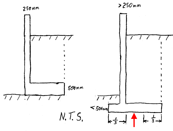
3. On your other thread, BAretired mentioned that the proportions of the wall are not right; I agree. The proposed geometry is not efficient. The loads are too near the toe (Very little lever arm to resist overturning moment. Loads too close to the toe to get proper distribution of load on the soil supporting the retaining wall.) The resultant load from supporting soil needs to the in the middle third of slab. Reproportion wall shape/dimensions for more favorable loading characteristics. Iterate for an improved design, change the initial assumed dimensions based on intermediate calculations. Don't expect to be right the first time.

RetainingWallGeometry-2_eankoo.png


4. Buy and use CRSI Design Guide for Cantilevered Retaining Walls that BAretired recommended.
Alternatively download US Army Corps of Engineers - Retaining and Flood Walls.

[idea]
[r2d2]
 
SlideRuleEra said:
See Page 5-48 of CalTrans Retaining Walls. I'm assuming the foundation soil has properties similar to backfill. Ok i get that, its the angle of friction between footing and foundation soil

Concerning the next step:

1. Take oldestguy's advice to determine the angle of repose (friction angle) and the unit weight of the proposed backfill. I'll bet unit weight and is less than the assumed 20 kN/m3. Do this even if you know the results will not be precise... some information is better than a guess. Use the values obtained for the design. IMHO, the time to be conservative is by increasing the safety factor, not by designing using "wrong" material properties. Ok, i will change all my values so that my design problem represents the real conditions as much as possible

2. How did you compute the surcharge load on the wall? Revisit that calculation by applying the 10 kPA load where it is (beginning 3 m from the wall) not at an assumed closer location. My simplified calcs indicate the surcharge will have minimal effect on the wall. Ignore the surcharge load contribution for resistance to overturning and sliding. I already ignored the surcharge load contribution for resistance to overturning and sliding.

Ok, I will recalculate my surcharge load, i think this is the main reason why my wall is overdesigned, due to the combination of the seismic load and surcharge load,
I still think its good to include a surcharge load near the wall which will represent compaction machinery, but i should not include this with the seismic force
Therefore my thought is to include the surcharge load of 10kPa exactly next to the wall for the compaction machinery but i should not include that in the seismic design.


3. On your other thread, BAretired mentioned that the proportions of the wall are not right; I agree. The proposed geometry is not efficient. The loads are too near the toe (Very little lever arm to resist overturning moment. Loads too close to the toe to get proper distribution of load on the soil supporting the retaining wall.) The resultant load from supporting soil needs to the in the middle third of slab. Reproportion wall shape/dimensions for more favorable loading characteristics. Iterate for an improved design, change the initial assumed dimensions based on intermediate calculations. Don't expect to be right the first time. I agree the alternative shape of wall you suggest is more efficient, however the reason i chose an inverse L-shaped wall and not an inverse T-shaped wall is because the wall is located exactly on the boundaries of the plot, therefore its not possible to extend my footing into the neighbouring plot, in addition i dont think its good idea to move the wall further inside the plot, its a waste of land. If my only coice is an inverse L-shaped wall what would be your suggestion to overcome this?

4. Buy and use CRSI Design Guide for Cantilevered Retaining Walls that BAretired recommended.
Alternatively download US Army Corps of Engineers - Retaining and Flood Walls. I will have a look in that
 
kellez said:
...my thought is to include the surcharge load of 10kPa exactly next to the wall for the compaction machinery...

I do not advise doing that. You will get back to very situation which prompted your original post: The wall appears overdesigned and you don't know why.

Apply the building's 10kPa load where it is... beginning 3 meters from the wall. Then you will know how much influence the permanent 10kPa load has on the wall.

There is no limit to other loads you can voluntarily superimpose. Apply a temporary construction (compaction) load adjacent to the wall... you are not "forced" to make it 10 kPA and can see what effect it has on the design. Also, the wall loading from compaction has different characteristics than a surcharge. Finally, the compaction loading is more of a point load (not a surcharge uniform distributed load) and it is temporary - a lower safety factor can be considered for a temporary load.

See "Pressure on Retaining Walls From Compaction Effort". In particular, look at "Figure 3".

If my only choice is an inverse L-shaped wall what would be your suggestion to overcome this?

I understand your reason of the inverse L-shaped wall, looks like the way to go.
See if you can excavate some for the wall's foundation slab. Just a depth that is reasonable without causing problems... even, say, a 0.5 meter deep excavation will help. Good idea to embed the slab in soil to minimize possible erosion problems (believe you told us frost depth is not a concern). The primary reason is to increase the amount of backfill on top of the slab... more weight to resist overturning/sliding and the centroid of this weight is located to help keep the foundation resultant force in the middle 1/3 of the slab.


[idea]
[r2d2]
 
SlideRuleEra said:
I do not advise doing that. You will get back to very situation which prompted your original post: The wall appears overdesigned and you don't know why.

Apply the building's 10kPa load where it is... beginning 3 meters from the wall. Then you will know how much influence the permanent 10kPa load has on the wall.

Ok i will apply the buildings surcharge load at 3 meters from the wall, which i have changed to 20kPa (i was wrong about the 10KPa).

I am looking into text books in order to find out how i can calculate the effect the surcharge load will have on the wall but i am having some difficulties. I have never tried to calculate this with a surcharge load that is at a certain distance from the wall.

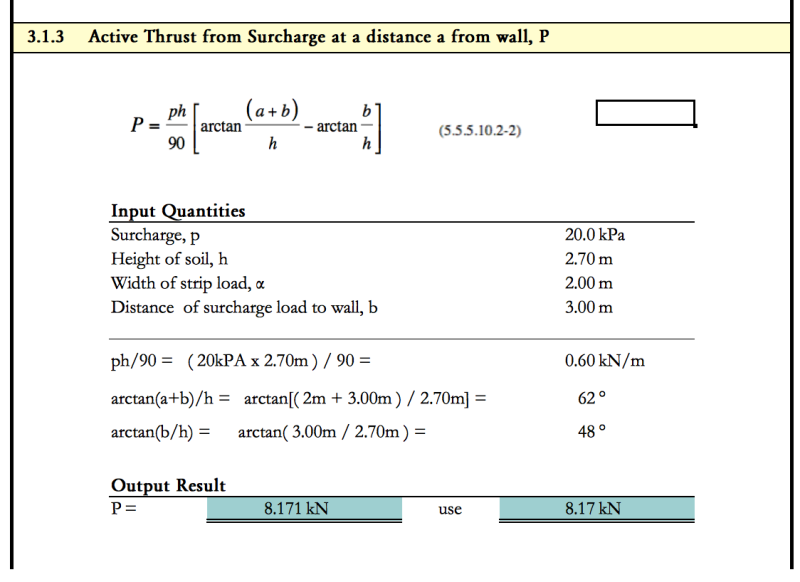
I have looked into the CalTrans Retaining Walls paper (page 39, equation (5.5.5.10.2-2)) you posted above and found this equation (see photo attached). This equation is used for a Uniformly Loaded Strip Parallel to the Wall, however my building load is not actually a strip but an RC concrete slab (raft foundation) parallel to the wall (approx, 10m x 13m) , therefore do you think I could consider this as a very wide strip or do i need to use another equation?

The value i get is 8.17kN, which seems a bit high considering that the building is 3.0 away from the wall. Also i do not know at what height (point) this acts on the wall, if you want to have a look i have attached the excel file below, its only one calculation. Am i wrong using this equation?

[URL unfurl="true"]https://res.cloudinary.com/engineering-com/raw/upload/v1515583756/tips/Surcharge_load_at_a_destance_x_from_wall_n7kqjx[/url]


Screen_Shot_2018-01-10_at_13.38.25_a4hkk4.png
 
Equation 5.5.5.10.2-3 tells you where the resultant force acts.

The ArcelorMittal piling handbook has an alternative formula. Worth checking a few different methods since they tend to be gross approximations, then picking a number that you're comfortable with. Another alternative might be good-old Coulomb wedges: change wedge angle to find the worst case.

Is the load 3m from the wall stem, or 3m from the heel/virtual face?
 
steveh49 said:
Equation 5.5.5.10.2-3 tells you where the resultant force acts.
thats a big equation, thanks, i will try it out

so i will need to determine this in order to check if the pressure actually acts on the wall, it could be lower than the base of the wall?

steveh49 said:
Is the load 3m from the wall stem, or 3m from the heel/virtual face?
Its 3.0meters from the wall stem
 
You might need to use equation 5.5.5.10.2-1 to determine the distribution over the height of the wall then integrate to find the resultant force. Equations 5.5.5.10.2-2 and -3 might assume that the wall extends below the horizontal pressure zone.

For a sanity check, consider that your load starts just 1.2m behind your heel/virtual face (or 1.5m, have you changed the sketch since first posting?) and extends over a large area, so isn't too different to the 'full surcharge' case shown on the sketch in your original post - ie a surcharge that continues up to the heel/vurtual face. The 'full surcharge' load is Q*Kh*H = 20kPa*0.33*2.7m = 17.8kN/m for 30degree friction angle backfill. Your first calculation (8.17kN/m) is half of that. Is it really an unreasonable load that needs to be reduced further? How accurate is the calculation since it doesn't have any factors that represent the shear strength of the soil? Is it impossible for there to be any other surcharge between the building and wall in future?


steveh49 said:
The 'full surcharge' load is Q*Kh*H = 20kPa*0.33*2.7m = 17.8kN/m for 30degree friction angle backfill. Your first calculation (8.17kN/m) is half of that. Is it really an unreasonable load that needs to be reduced further? How accurate is the calculation since it doesn't have any factors that represent the shear strength of the soil? Is it impossible for there to be any other surcharge between the building and wall in future?

I dont think there will be any surcharge load in the future, however, first i would like to design my wall using the most accurate load cases that best describe the real life loads, and then i can add any additional loads i want.

No, the 8.17kN/m i calculated is not an unreasonable value, however, most importantly i need to determine at what height the surcharge load will act on the wall, which i think it will act below the base of the wall. It will probably act upon the footing/foundation of the wall however i will neglect that since its a favourable action against sliding and overturning.


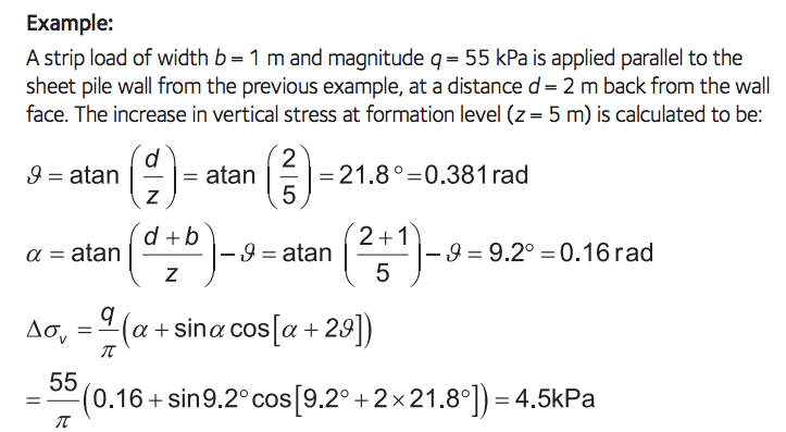
I had a look in ArcelorMittal piling handbook and found another equation for determining the effect of a surcharge load on the wall, a lot simpler than the one found in CalTrans Retaining Walls the equation is shown below and can be found at page 137-139.

One observation is that again the equation is not using any soil material properties. The equation is shown below with an example

Screen_Shot_2018-01-10_at_18.56.24_zlb5gm.png


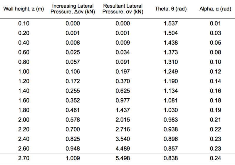
I used this equation in excel and these are my results

INPUT DATA:
Surcharge, q = 20.00kPa
Distance, d = 3.00m
Strip load width, b = 2.00m
Height of wall, h = 2.70m

First I calculated the Increasing Lateral Pressure, Δσv (kN) and then I sum up the values to get the resultant lateral pressure, Is this correct?

Another observation is that if a plot the force diagram of the resultant lateral pressure, it will be triangular, which i think its not realistic in such a load case.
do you guys think i should use the The Boussinesq Equation

Screen_Shot_2018-01-10_at_19.20.32_d7r80z.png
 
Status
Not open for further replies.

Part and Inventory Search

Sponsor