Continue to Site

Eng-Tips is the largest engineering community on the Internet

Intelligent Work Forums for Engineering Professionals

  • Congratulations waross on being selected by the Eng-Tips community for having the most helpful posts in the forums last week. Way to Go!

Guidance for the Design of a Reinforced Concrete Retaining Wall 5

Status
Not open for further replies.

kellez

Civil/Environmental
Nov 5, 2011
276
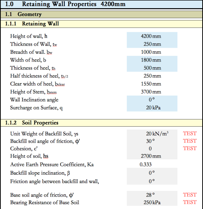
Hello everyone, please find attached a drawing of the retaining wall i am designing according to EC7 together with an excel file of my calculations.
Its a cantilever L-shaped reinforced concrete wall comprised of a stem and foundation slab.

Backfill soil is well graded gravel with unitweight = 20kN/m3 and angle of friction = 25degrees (conservative value)
Wall height is 4.20m, Height of soil retained by wall is 2.70meters.
Surcharge load = 10kPa, A seismic force has also been considered.

According to my calculations my problem here is that the foundation of the wall needs to be at least 1.80meters wide in order to get a safety factor of 0.94 against sliding, which i think its too much for this design.
So for a 2.70m hight soil i get a 1.80m wide foundation slab in order to resist sliding. Dont you guys think that This is a really expensive design? am i doing something wrong? or did i get tit right?

The excel file is sectioned as follows:

0. Retaining Wall Properties
1. Gross Pressure Method
2. Eurocode Comb 1
3. Eurocode Comb 2
4. Seismic
5. Bending Reinforcement
6. Deflection (not complete)

Can you guys please have a look at my work and help figure this out? does the wall foundation need to be that wide?

[URL unfurl="true"]https://res.cloudinary.com/engineering-com/image/upload/v1514841058/tips/Retaining_Wall_Details_-_forum_lrme3i.pdf[/url]

[URL unfurl="true"]https://res.cloudinary.com/engineering-com/raw/upload/v1514841074/tips/Retaining_Wall_Design_y9vhvs.ods[/url]
 
Replies continue below

Recommended for you

kellez said:
I have never tried to calculate this with a surcharge load that is at a certain distance from the wall.

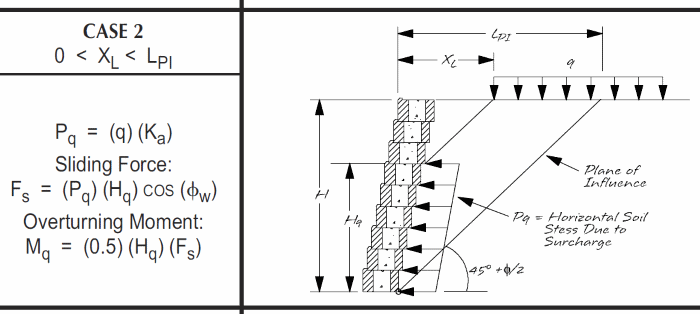
Fine, now you are making progress. You want the mathematical model to "fit" the problem... not just be application of your existing skill set. But the solution does not have to always be complicated. Since this is your first retaining wall design, suggest starting with a semi-graphical solution to get an understanding of how the remote surcharge affects the wall. I like the simplified method shown and explained on pages 28 & 29 of Allan Block Retaining Wall Engineering Manual.

AlanBlockDiagram-1_uio98g.png

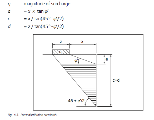
The Arcelor Mittal Piling Handbook that steveh49 mentioned has a similar approach - see Chapter 4.

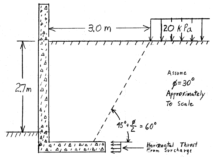
For your wall, I get approximately 3.3 kN thrust (assuming the foundation slab is 0.5 meters thick).

AlanBlockSolution-1_jjprrz.png


kellez said:
I would like to design my wall using the most accurate load cases that best describe the real life loads, and then I can add any additional loads I want.

Good, I have a couple of suggestions for additional minor loads to check. But you should have enough info now to make a first order iterative design. Let's see what you come up with.

[idea]
[r2d2]
 
I am working on it, i will post my sketch in a bit

 
For external stability, it is usual to calculate the destabilising forces that act on the virtual face of the wall. In that case, your surcharge load is 1.2~1.5m away depending on what your current base width is. This would increase the load acting on the wall compared with assessing the load based on the 3m distance of the surcharge from the stem.

The Piling Handbook gives you the distribution of load vs depth below ground. You have to work out the height of the resultant by integration. For information, the diagram and equations from your previous post [now deleted] were under the heading "Concentrated and Linear Surcharge" in previous editions of the Piling Handbook.

From a few posts ago: "First I calculated the Increasing Lateral Pressure, Δσv (kN) and then I sum up the values to get the resultant lateral pressure, Is this correct?" This isn't correct. Δσv is in kPa; it's the vertical pressure at a point in the soil due to the surcharge and varies depending on the location of the point in question relative to the surcharge load. You multiply Δσv by the horizontal pressure coefficient to get the lateral pressure, then integrate the lateral pressure distribution to get the resultant total force and location of the resultant.

The current Piling Handbook appears to give a couple of different methods for assessing the lateral pressure resulting from the area surcharge, and the Allan Block method is different again. There will be other methods out there. I hope it's clear that these equations only give order-of-magnitude estimates of the load applied to the wall. If the load due to this surcharge is a significant part of the total horizontal load, tread carefully.


steveh49 said:
For external stability, it is usual to calculate the destabilising forces that act on the virtual face of the wall. In that case, your surcharge load is 1.2~1.5m away depending on what your current base width is. This would increase the load acting on the wall compared with assessing the load based on the 3m distance of the surcharge from the stem.

That is a valid point you made there, i will adjust my calculations and post my sketch. I need to take this step by step. I will show you my sketch to let me know if i am correct
 
Ok this is where i am right now

I have used the equations in The Piling Handbook (see below) in order to determine how the load is distributed

Screen_Shot_2018-01-11_at_15.09.05_ff2y9g.png


Therefore, I calculated a, c and d (see below)

Screen_Shot_2018-01-11_at_15.07.12_nsynlr.png


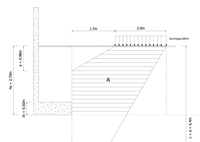
And this is the shape I have come up with

CASE 1: STRIP LOADING

Screen_Shot_2018-01-11_at_15.39.16_tj9q5a.png


CASE 2: INFINITE LOADING - THIS IS MORE REALISTIC FOR MY CASE SINCE THE BUILDING IS 10m wide


Screen_Shot_2018-01-11_at_18.54.07_tjzprq.png


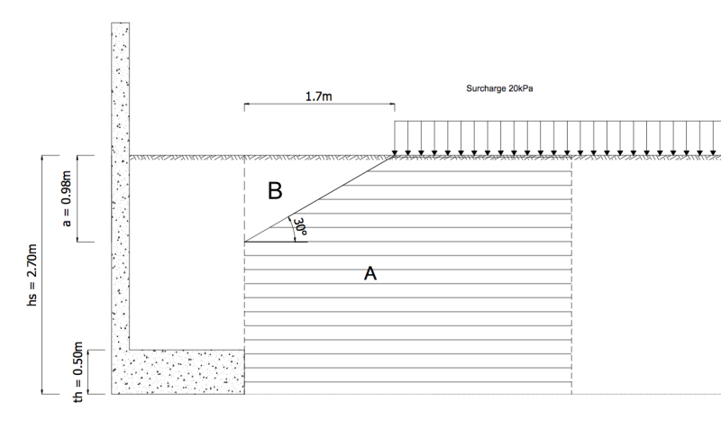
My thinking now is that I should first calculate the whole surcharge load as if it was exactly next to the wall

Active thrust due to surcharge: Pq = Ka x q x h = 0.33 x 20 x 2.70 = 18.0kN

Then i should calculate the surcharge load according to triangle B

Active thrust due to surcharge from Triangle B: Pq = Ka x q x a/2 = 0.33 x 20 x (0.98/2) = 3.28 kN

now subtract B from A

Active thrust due to surcharge from Shape A: 18.0kN - 3.28 kN = 14.72 kN

Therefore the total thrust of the surcharge load is 14.72 kN

Everyone agrees with this?
 
steveh49 said:
For external stability, it is usual to calculate the destabilizing forces that act on the virtual face of the wall. In that case, your surcharge load is 1.2~1.5m away depending on what your current base width is. This would increase the load acting on the wall compared with assessing the load based on the 3m distance of the surcharge from the stem.

Thank you steveh49, I did not know that. It makes sense.

kellez - The 14.7kN surcharge thrust sounds good to me... for an initial trial. Make the (preliminary) calcs for all the loads, you have to start somewhere - don't "wait" until you have "better" information. The preliminary results will guide you to the next step.

Did you decide to keep the footing sitting on top of existing ground (total height 2.7m) ?

The surcharge loading will be larger (more important) than I originally estimated. Is an allowance for the building's live load included in the 20kPA value? If the building is a warehouse or for heavy equipment live load may be considerable... not so much for an office or residence.

Remote_Surcharge_Loading-1_fslnra.png


[idea]
[r2d2]
 

SlideRuleEra said:
Did you decide to keep the footing sitting on top of existing ground (total height 2.7m) ?

Yes I will keep it that way for now and carry out the design as it is, i will see how it goes an decide if i should excavate and site the wall at a lower level within the excavation.


SlideRuleEra said:
Is an allowance for the building's live load included in the 20kPA value? If the building is a warehouse or for heavy equipment live load may be considerable... not so much for an office or residence.

No i did not account for a live load in the surcharge load, however this is only a 1-story residence. Its a reinforced concrete structure with a 45cm thick foundation slab/raft foundation, thats why the 20kPa surcharge load.


I am currently working on my calculations and checking everything, i did find some careless mistakes, that also contributed to the overdesign, however now my surcharge has increased as well, so i should be back at the same design as before. I will do my calculation and let you know

Any advise on how to apply the seismic load, I have used the Seed and Whitman Method to determine the seismic load, and then added it to the existing thrust from soil and thrust from surcharge.

However i think the Seed and Whitman Method is way to conservative than the Monobe Okabe method which is also suggested by the Eurocode 8, and because my main issue here is the


I have one very important question that greatly affects the design:


Load case combinations and safety factors greatly affect the design, therefore my question is, The surcharge load from the building is considered as a permanent load right?
 
I think deepening the excavation will result in diminishing returns as you end up increasing the amount of surcharge and soil pressure the wall sees. But that's just a thought.
 
kellez said:
Any advise on how to apply the seismic load, I have used the Seed and Whitman Method to determine the seismic load...

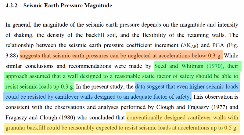
Seed & Whitman is as good as any. I see that the design ground acceleration = 0.25g. Take a look at Development of Improved Procedures for Seismic Design of Buried and Partially Buried Structures, published by the Pacific Earthquake Engineering Research Center. In particular, see the "Conclusions & Recommendations" on page 157:

Improved_Seismic_Design-1_ngumgx.png


More about that in a minute.

kellez said:
Load case combinations and safety factors greatly affect the design, therefore my question is, The surcharge load from the building is considered as a permanent load right?

Yes, I would consider the building's surcharge load as permanent for horizontal thrust on the wall. As discussed earlier, no credit for the surcharge to resist sliding or overturning.

Considering load combinations - for this first order calculation I suggest applying the following loads simultaneously:

1. Thrust From Soil, with Overturning & Sliding Safety Factors of 1.5

2. Thrust From Building Surcharge, with Overturning & Sliding Safety Factors of 1.5

3. Seismic Force, with Overturning & Sliding Safety Factors of 1.0 (Recommendations given above are used as justification for no added safety factor).

Make the calcs... let's see what you get. This is a wonderful project... you'll learn a lot more by having to deal with what I believe is a first effort with "issues". There will be other concerns to address later.

jayrod12 is right, but like everything else there may be compromise advantages to an excavated foundation. First, make the above calcs.

[idea]
[r2d2]
 
SlideRuleEra said:
Yes, I would consider the building's surcharge load as permanent for horizontal thrust on the wall. DONE

As discussed earlier, no credit for the surcharge to resist sliding or overturning. DONE

Considering load combinations - for this first order calculation I suggest applying the following loads simultaneously:

1. Thrust From Soil, with Overturning & Sliding Safety Factors of 1.5

2. Thrust From Building Surcharge, with Overturning & Sliding Safety Factors of 1.5

3. Seismic Force, with Overturning & Sliding Safety Factors of 1.0 (Recommendations given above are used as justification for no added safety factor).

The load combination I have used is 1) Thrust from soil + 2) Thrust from building surcharge + 3) Seismic force

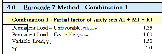
I am using 2 types of load combinations, according to eurocode, safety factors are shown below, Combination 1 is used to factor the loads, Combination 2 is used to factor the material properties


Screen_Shot_2018-01-15_at_11.10.17_v05kru.png
Screen_Shot_2018-01-15_at_11.10.36_sdenxh.png


For the seismic force i am using a safety factor of 1.0 as you suggested


Make the calcs... let's see what you get. This is a wonderful project... you'll learn a lot more by having to deal with what I believe is a first effort with "issues". There will be other concerns to address later.

Indeed i have learned a lot up to now while trying to solve all the issues with your help and everyone elses help.

jayrod12 is right, but like everything else there may be compromise advantages to an excavated foundation. First, make the above calcs.
 
I have done the calculations using the following properties for the wall and soil

THE Retaining Wall Foundation is still at 1.80m wide but i have more confidence in my calculations now
As you can see from the results below I still have an issue with when the seismic load is added in the calculations any advice on that?


Screen_Shot_2018-01-15_at_12.56.32_nknivq.png


These are the results i get

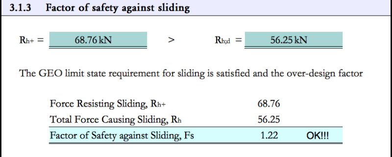
SLIDING: EUROCODE COMBINATION 1

Screen_Shot_2018-01-15_at_12.58.33_kc6uyb.png


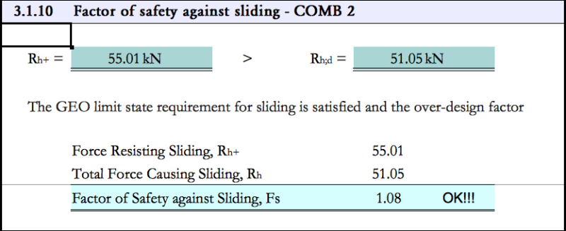
SLIDING: EUROCODE COMBINATION 2

Screen_Shot_2018-01-15_at_13.06.13_wkf2zo.png


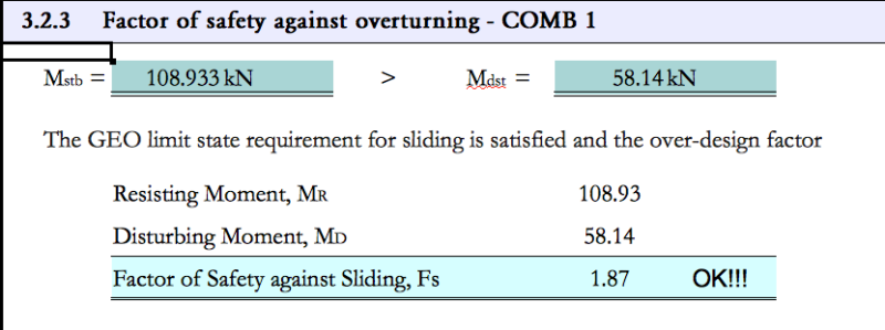
OVERTURNING: EUROCODE COMBINATION 1

Screen_Shot_2018-01-15_at_13.02.11_uapgoh.png


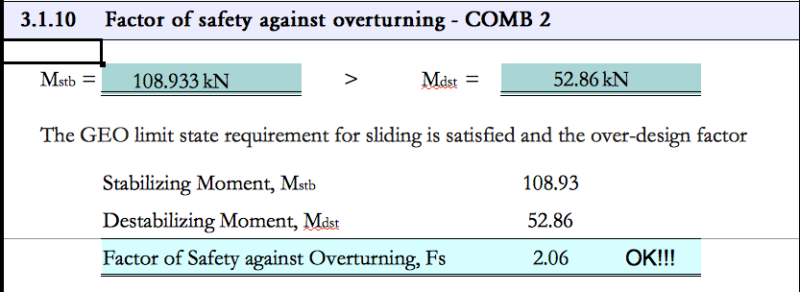
OVERTURNING: EUROCODE COMBINATION 2

Screen_Shot_2018-01-15_at_13.03.12_xpubux.png


SEISMIC: EUROCODE COMBINATION 1

For the seismic load case, I have calculated the 1) Total Horizontal Force due to soil + 2)Total Horizontal Force due Surcharge, + 3) Seismic force according to the Seed and Whitman Method which i think is a bit more conservative than the Mononobe Okabe Method. I will also give Mononbe Method a try and see


Screen_Shot_2018-01-15_at_13.23.13_iwofoj.png


As you can see my SF for seismic load case is still below 1, this is my biggest issue now, i need to concentrate on this one now
 
I tried calculating the total horizontal thrust using the Mononobe Okabe method but i have one issue.
The example I am following is only about a gravity mass retaining wall therefore there is no wall footing/foundation thereofe there is no soil on top of the foundation to resist sliding and overturning,

Therefore my question now is:

What do i need to do in order to take into account the resistance to sliding and overturning that is provided by the soil which sits on top of the footing/foundation.
Another way to set the question is how much of the soil sitting on top of the footing will contribute to the seismic force and how much will contribute to the resisitnace against sliding/overturning?
 
One more question regarding the Mononobe Okabe method

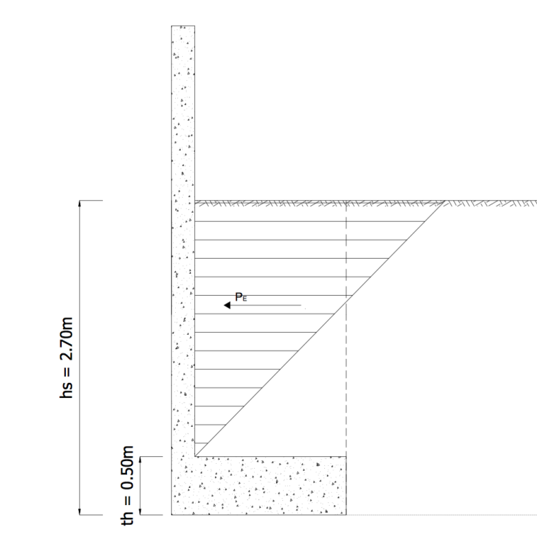
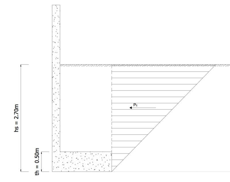
Which triangle from the two below best describes the seismic force

Screen_Shot_2018-01-15_at_18.14.04_zwbamd.png


Screen_Shot_2018-01-15_at_18.13.42_ctyzp5.png
 
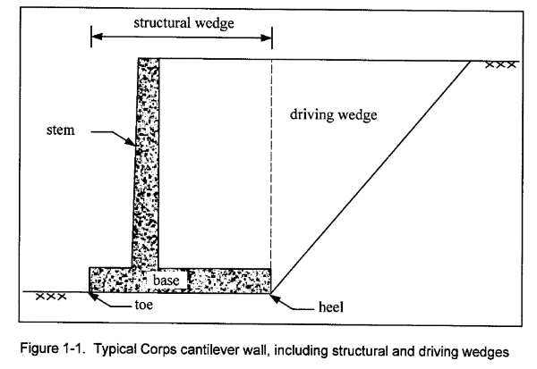
kellez - Concerning how seismic force acts on a cantilever retaining wall. Your second sketch is in accordance with US Army Corps on Engineers practice:

Driving_Wedge-1_h1qsbb.png


Seismic force comes from the "driving wedge" and acts on the "structural wedge". See Seismic Analysis of Cantilever Retaining Walls.

I'm still working on a response to your spreadsheet results. We have some more fundamental issues to look at. Will take me a while to put together an explanation... should have something later today.

[idea]
[r2d2]
 
kellez - Good, you made the initial cals... now you can begin to iterate the design. I'm not familiar with the Eurocodes, so can't help you on that. But the calcs indicate that "something" is wrong. Refer to my comments on January 5:

SlideRuleEra said:
The resultant load from supporting soil needs to the in the middle third of slab. Reproportion wall shape/dimensions for more favorable loading characteristics.

Believe me, I don't make this stuff up. [smile]

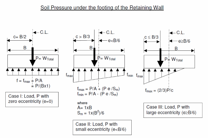
Soil_Pressure-1_yi9bye.png


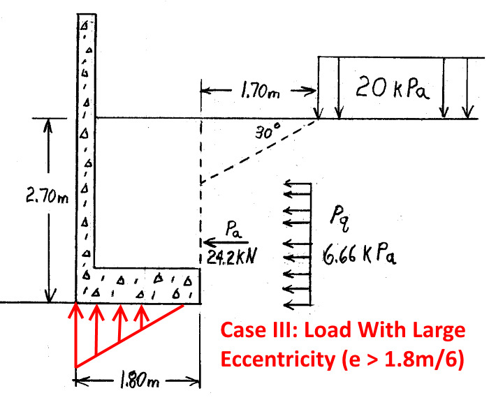
You have checked overturning and sliding, but don't appear to have checked the more important soil pressure distribution under the footing. Having soil pressure distribution Case I or Case II is essential for basic loading conditions. For "extraordinary" loading, a limited amount of Case III may be considered acceptable.

Evaluate the proposed geometry (base is 1.80 meter long). Use the basic calculated active thrust from the soil and active thrust from the surcharge... NO adjustments, NO added safety factors, just the calculated values. For the time being, ignore seismic loading too.

If my math is right (I find metric to be very "difficult"... my problem, not yours), the soil pressure distribution under the footing is Class III... too much eccentricity in the loading.

Retaining_Wall_Loads-1_ewxndu.png


The footing geometry MUST be changed for it to work properly with the existing assumptions. The wall does not fail by being Case III, but it indicates that the design is absolutely NOT right. This is your project, think about how do you want to proceed. There are several options to consider, propose what you would do.

[idea]
[r2d2]
 
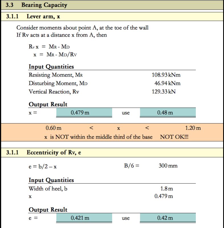
You are right i need to deal with this before i move to the seismic load. I did carry out the calculations for eccentricity and bearing capacity of the foundation, please see below.
You are right the vertical force of the wall is acting outside of the middle third of the wall base, which will cause an increase in pressure on the ground below the foundation.
this is due to the fact that the weight of the wall is not spread uniformly across the whole area of the foundation.

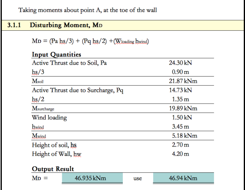
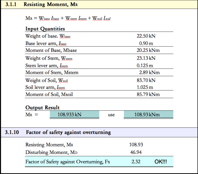
NOTES REGARDING MY CALCULATIONS:

As you will notice I have also added a small force for wind loading, what do you think about that (shall i remove it)?
Shall i also consider the surcharge acting on the base of the wall when calculating the Resisting Moment?


Screen_Shot_2018-01-16_at_09.20.24_jfosza.png


Screen_Shot_2018-01-16_at_09.20.33_vt7vpq.png


Screen_Shot_2018-01-16_at_09.21.02_eios3y.png
 
kellez said:
...added a small force for wind loading, what do you think about that (shall i remove it)?

The chances of having design wind loading AND a design earthquake, at the same time are very small. The traditional approach is to pick the greater of the two loads, and ignore the other - I agree with that. Chances are the seismic loading will govern for this project.

kellez said:
Shall i also consider the surcharge acting on the base of the wall when calculating the Resisting Moment?

IMHO,that is a reasonable potential solution to consider. On this project, if the heel slab was directly below the surcharge load, that should work. But the slab is not below the load, so my answer to that is no.

The surcharge load is fairly close the the heel slab, so the surcharge may put some vertical loading on the heel slab. But the soil properties are in doubt. Without detail knowledge of the soil properties and control of backfill placement, I would not consider that approach either.

[idea]
[r2d2]
 
Kelles said:
NOTES REGARDING MY CALCULATIONS:

As you will notice I have also added a small force for wind loading, what do you think about that (shall i remove it)?
Shall i also consider the surcharge acting on the base of the wall when calculating the Resisting Moment?

Just to be clear, both questions quoted above, are in regards to the case of determining the eccentricity of the wall.
 
The eccentricity of the wall needs to be calculated for more than one load combination. The basic combination is called "Usual Loading" by the US Army Corps of Engineers. For this project's usual loading the horizontal active thrust from the soil plus the horizontal active thrust from the surcharge are resisted the weight of the concrete stem and heel slab plus the weight of the backfill directly above the heel slab. IMHO, the horizontal active thrust from the surcharge acts on the structural wedge and the horizontal projection of the heel slab.

If the usual loading eccentricity is too large (which it is on the current design)... stop. Take the steps needed (often redesign of wall geometry) to lower the eccentricity before considering other load combinations (which may include wind loading).

This is a good time to bring up what some may consider a minor issue. The assumed weight of concrete seems high, 25 kN/m[sup]3[/sup] (159 PCF). In the US, 150 PCF (23.6 kN/m[sup]3[/sup]) is considered the weight of "normal" reinforced concrete. This value is typically sightly conservative... if (per the usual case) the concrete has to be supported by falsework and forms. For uplift and buoyancy calculations, I consider 150 PCF to be overly optimistic. Note that for this retaining wall the weight of concrete is most important for resisting the overturning moment (uplift). For uplift/buoyancy I use 145 PCF (22.8 kN/m[sup]3[/sup]).

Just suggesting that you use a realistic value of concrete weight for this project... whatever that value may be. What on first glance "seems" conservative, may not be.

[idea]
[r2d2]
 
Going back a bit

SlideRuleEra said:
1. Thrust From Soil, with Overturning & Sliding Safety Factors of 1.5 EUROCODE suggests a factor of safety of 1.35, this is what i used up to now

2. Thrust From Building Surcharge, with Overturning & Sliding Safety Factors of 1.5 if surcharge is considered a permanent load which it is in this example then the factor of safety according to Eurocode is again 1.35[ this is what i used up to now/color]

3. Seismic Force, with Overturning & Sliding Safety Factors of 1.0 (Recommendations given above are used as justification for no added safety factor). Eurocode dictates a seismic coefficient depending on the location of the structure and no factor of safety is provided therefore 1.0 is acceptable.


what are your thoughts on the eurocode factors of safety, NOTE: for variable surcharge loads Eurocode suggests a factor of safety of 1.5 but since by surcharge load is permanent i will use 1.35

 
Status
Not open for further replies.

Part and Inventory Search

Sponsor