Continue to Site

Eng-Tips is the largest engineering community on the Internet

Intelligent Work Forums for Engineering Professionals

  • Congratulations waross on being selected by the Eng-Tips community for having the most helpful posts in the forums last week. Way to Go!

Guidance for the Design of a Reinforced Concrete Retaining Wall 5

Status
Not open for further replies.

kellez

Civil/Environmental
Nov 5, 2011
276
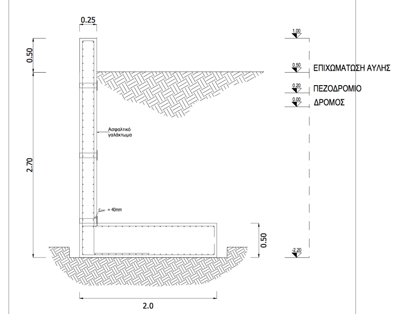
Hello everyone, please find attached a drawing of the retaining wall i am designing according to EC7 together with an excel file of my calculations.
Its a cantilever L-shaped reinforced concrete wall comprised of a stem and foundation slab.

Backfill soil is well graded gravel with unitweight = 20kN/m3 and angle of friction = 25degrees (conservative value)
Wall height is 4.20m, Height of soil retained by wall is 2.70meters.
Surcharge load = 10kPa, A seismic force has also been considered.

According to my calculations my problem here is that the foundation of the wall needs to be at least 1.80meters wide in order to get a safety factor of 0.94 against sliding, which i think its too much for this design.
So for a 2.70m hight soil i get a 1.80m wide foundation slab in order to resist sliding. Dont you guys think that This is a really expensive design? am i doing something wrong? or did i get tit right?

The excel file is sectioned as follows:

0. Retaining Wall Properties
1. Gross Pressure Method
2. Eurocode Comb 1
3. Eurocode Comb 2
4. Seismic
5. Bending Reinforcement
6. Deflection (not complete)

Can you guys please have a look at my work and help figure this out? does the wall foundation need to be that wide?

[URL unfurl="true"]https://res.cloudinary.com/engineering-com/image/upload/v1514841058/tips/Retaining_Wall_Details_-_forum_lrme3i.pdf[/url]

[URL unfurl="true"]https://res.cloudinary.com/engineering-com/raw/upload/v1514841074/tips/Retaining_Wall_Design_y9vhvs.ods[/url]
 
Replies continue below

Recommended for you

There is no budget at all, thats why i am taking it slow. :)

Well Eurocode suggests a minimum amount of reinforcement on the compression side to avoid cracking.
After your comments i decided to increase the bar size at 14mm thick bars and increase the spacing at 160mm about 6 bars per meter run


Ok now i have a very specialised question regarding the design of the retaining wall.

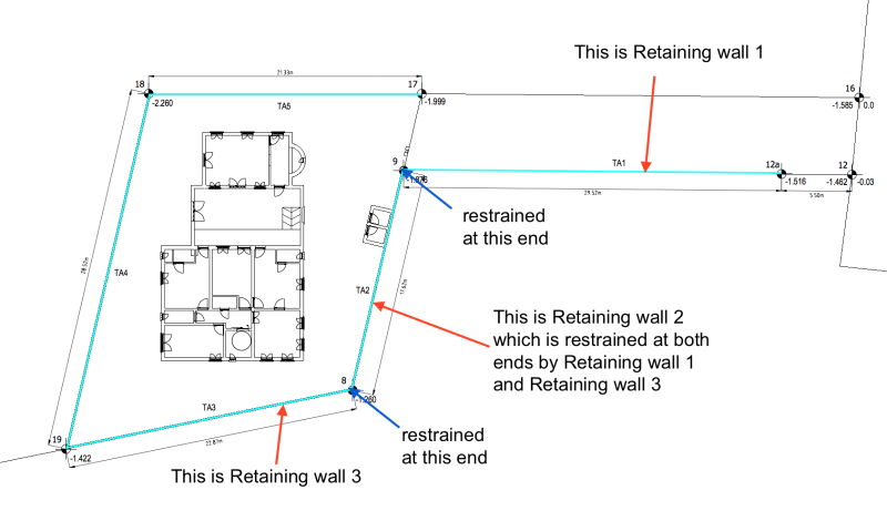
Please have a look at the picture below,
Lets consider Retaining Wall 2, as you can see this wall is restrained at both ends by Retaining Walls 1 and 3, for certain their foundation slab will be connected.
which means there is no way that this wall could actually slide, right?

when designing a wall we usually design the wall by considering only 1 meter of the wall, we do not actually consider the wall as a whole.
therefore do you guys think i could reduce the size of my foundation slab by taking into consideration the fact that the wall is restrained at both ends?
My biggest issue with the wall design was resistance against sliding therefore i am thinking that this could be one way to reduce the width of the slab for only retaining wall 2

what do you guys think?

[URL unfurl="true"]https://res.cloudinary.com/engineering-com/image/upload/v1519234569/tips/Screen_Shot_2018-02-21_at_19.16.05_bprcd4.pdf[/url]

Screen_Shot_2018-02-21_at_19.16.05_bqiqsg.png
 
There is no budget at all, thats why i am taking it slow. :)

Well Eurocode suggests a minimum amount of reinforcement on the compression side to avoid cracking.
After your comments i decided to increase the bar size at 14mm thick bars and increase the spacing at 160mm about 6 bars per meter run


Ok now i have a very specialised question regarding the design of the retaining wall.

Please have a look at the picture below,
Lets consider Retaining Wall 2, as you can see this wall is restrained at both ends by Retaining Walls 1 and 3, for certain their foundation slab will be connected.
which means there is no way that this wall could actually slide, right?

when designing a wall we usually design the wall by considering only 1 meter of the wall, we do not actually consider the wall as a whole.
therefore do you guys think i could reduce the size of my foundation slab by taking into consideration the fact that the wall is restrained at both ends?
My biggest issue with the wall design was resistance against sliding therefore i am thinking that this could be one way to reduce the width of the slab for only retaining wall 2

what do you guys think?

Screen_Shot_2018-02-21_at_19.16.05_bqiqsg.png
 
kellez said:
...reduce the size of my foundation slab by taking into consideration the fact that the wall is restrained at both ends?

How far from the corner (horizontally) is the proposed "reduced size foundation" extended? How is that calculated (with certainty)?

IMHO, quit trying to "save money" by cutting corners on permanent materials. Real savings come from logical, simple design and reduced construction labor.

The Contractor will have wall concrete forms that he reuses many times along the length of the wall. If the design changes in the corners, he now has to do "special" (expensive) forming... just to "save" a token amount of (cheap) concrete.
Note: By "cheap" I mean to the Contractor. For example the "cost" to form, place, finish a certain concrete pour with, say 18 m[sup]3[/sup] is virtually identical to 20 m[sup]3[/sup]. The only money "saved" is the Contractor's cost for 2 m[sup]3[/sup] of concrete... and it took much extra labor to do that.

[idea]
[r2d2]
 
I am not just trying to reduce costs here, i am actually trying to learn.
This thought came to my mind once i started thinking about the wall as a whole and how it will react under an earthquake as whole,
i think this is only logical since when designing a wall we only think of a meter run of the wall. therefore i had to ask.
any question i ask here is only to check what other more experienced engineers would do.


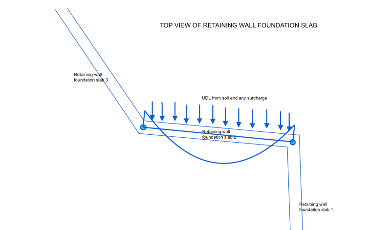
Ok lets say that the point which is furthest from the restrained points, that is the middle of the wall is under loading and its about to slide,
in order for it to slide and move, the wall and foundation slab will need to bend and a bending moment will be created on the foundation slab of the wall.
As a matter of fact the foundation will act as beam supporting a floor slab. please look at the picture below where the wall foundation slab is illustrated as a beam.

while drawing the picture below i also thought that its wrong to only consider the loading only on one wall, therefore the loading on the other walls will need to be also considered.
anyway, i think i am overcomplicating this, i am already finished with the design of the wall but just discussing

Screen_Shot_2018-02-21_at_21.52.25_vzju85.png
 
what would be the use of these joints?

my guess is to disconnect the walls so that they do not affect each other,
however their foundation slab would still be connected.
 
kellez (20 Feb 2018) said:
Can I save some steel by using 10mm bars on the compression side instead of 12mm?

I misinterpreted your 20 Feb comment about permanent material reduction, sorry about that, let's move on:

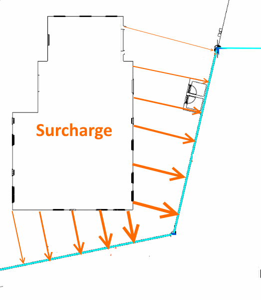
It is wrong to consider only one wall, but there are limits to what can reasonably be modeled. Consider the surcharge is a little more detail, it is different at every location on the wall and it acts in all directions simultaneously. Even this marked up sketch is a gross simplification:

Plan_View-1_e8hvms.png


Also, go back the very beginning of this thread. Just how accurate are soil properties? There is no point in, say, precise 4 significant digit calcs when the input data (including model assumptions) are estimated to 2 significant digit (at best) accuracy.

Your latest sketch shows another good point: Longitudinal steel is important. Not all support is provided by the wall resisting vertical bending.

A final point, everything interacts, just like the corner situation you described. Problem is, often the interactions are often unpredictable. I'll give you an example, sorry I did not take a picture of the following:

A timber industrial dock in seawater remained standing even though low tide revealed that far more than half the timber piling had been totally cut by marine borers. The timber stringers, tied with nails to the (suspended in midair) timber pile caps, were "sagging". These lines of stringers were acting just like the main cables of a suspension bridge to support the deck between the few (randomly spaced) piling that somehow were still standing. Could anyone predict that dock had not collapsed... I don't think so.

Make the best representative assumptions possible, then be conservative... don't look for shortcuts.

[idea]
[r2d2]
 
OP said:
my guess is to disconnect the walls so that they do not affect each other,
however their foundation slab would still be connected.

You can put control joints in the footing at the corners if you like... not likely needed... you can also put control joints in the footing at locations in the wall, but, also not likely needed.

Dik
 
control joints it what we also call expansion joints?
 
generally to accommodate shrinkage; an expansion joint is normally formed, a control joint sawcut...

Dik
 
Some other concerns regarding the construction of the wall:

1) I am thinking of using an expansion joint (that runs across the whole height of the wall stem) every 12m.
wall and steel reinforcement discontinuity.
2) the wall height without considering the footing is 2.7m, is it ok to pour this wall in one go?
3) is there going to be an issue pouring the concrete from a height of 2.7m?
 
kellez said:
I am actually trying to learn.
...and you are doing a good job, keep at it.

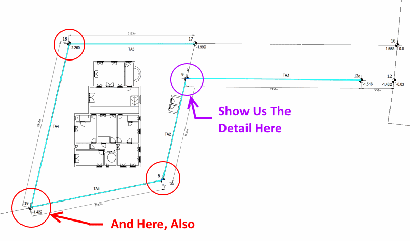
Before getting to your most recent 3 questions (which are good ones), keep working on the "hard" stuff. As the old saying goes, "the devil is in the details". How those 4 corners (3 exterior, 1 interior) are designed is not something to leave up to the Contractor.

The most difficult are the exterior corners, soil pressure is tending to "open" up the walls. This is your problem. We talked about the (easier) interior corner before... let's see what you have in mind on that one, too.

RW-Plan-Corners-1_ylwdn9.png


[idea]
[r2d2]
 
Yes reinforcements at wall corners is very important i know, however before we go there, i would like to talk about the reinforcement of the wall and footing.
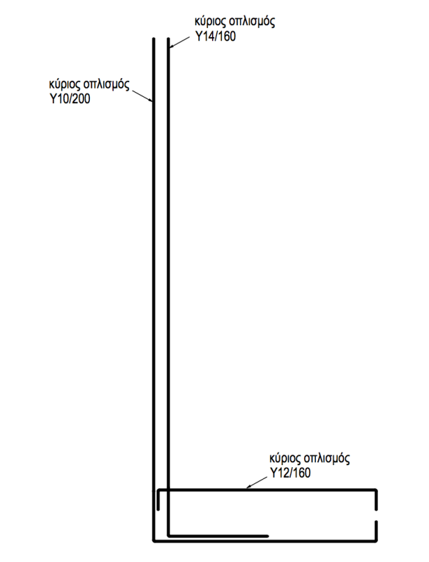
Below is the final design of the wall followed by two different arrangements for the reinforcement

Screen_Shot_2018-02-23_at_17.01.46_yifkjp.png


Initially i was thinking of using bars that run straight from the top of the wall down into the footing with an angle of 90 degrees
and continue to form the reinforcement of the footing. therefore one continues bar that forms the wall reinforcement and footing lower reinforcement as shown below

Screen_Shot_2018-02-23_at_17.01.33_kmkvwg.png


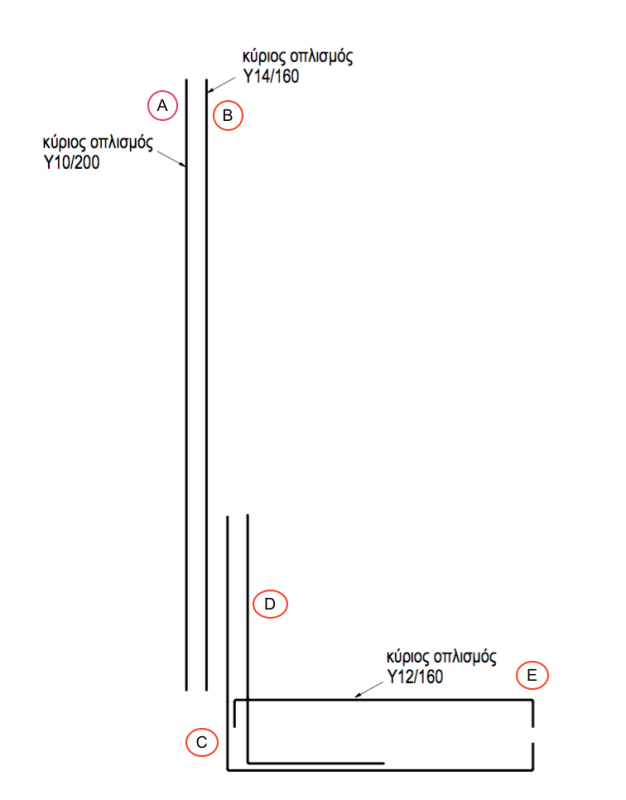
However after talking to the steel fabricator, he said that it would be hard to handle this kind of bar due to the height of the wall,
therefore he suggested using starter bars so that the bars are not that big (see drawing below). i think he is right, what do you guys think is there any major issue when using starter bars?

Screen_Shot_2018-02-23_at_17.07.09_zfessp.png
 
Kellez said:
Yes reinforcements at wall corners is very important...

I'm not talking about reinforcement in the corners. Forget the corner reinforcement for a bit, if the exterior corners are not designed correctly, the wall may collapse because of insufficient resistance to overturning moment.

Concerning the rebar detail shown today, the fabricator is right. I see that you are keeping the 10mm bars... I want you to do a simple experiment. Pickup one 10mm bar that is about 2.7 meters long and hold it only at the bottom, with the bar pointing straight up. Does it "bend" under it's own weight?

Another advantage to large reinforcing bars is that they have significant structural properties as steel members. The "stronger" bars allow the tied reinforcing cage to be more self supporting inside the wall forms (before and during concrete wall placement). IMHO, even 14mm bars (on both wall faces) are marginal (for self-support purposes on this wall). Remember the reinforcing cage has a lot of forces on it during concrete placement... and if the reinforcement ends up in the wrong place there will be "problems", as you know.


[idea]
[r2d2]
 
Thank you all for the assistance.
 
Where are the two last posts of this thread which i posted yesterday?
 
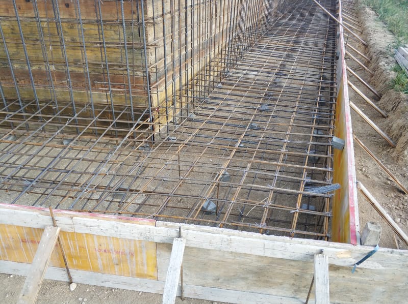
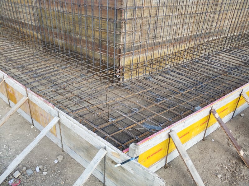
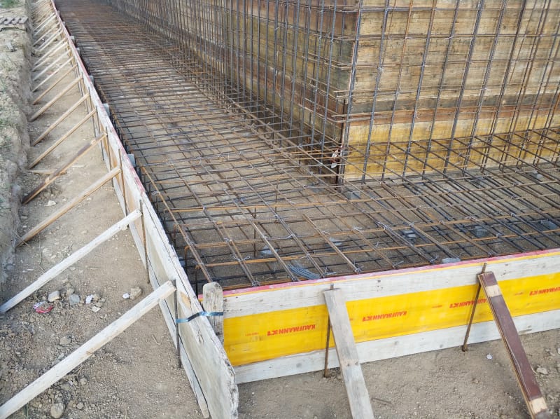
Hello everyone, the construction of the wall has started, we are currently fixing the reinforcement of the footing together
with the starter bars of the wall above in order to pour the footing.

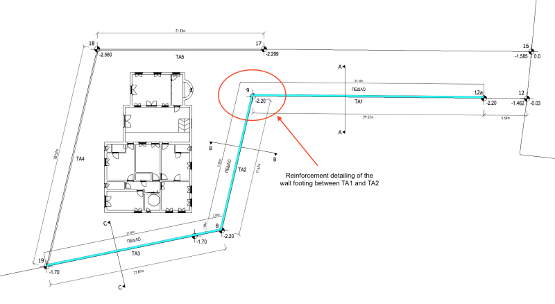
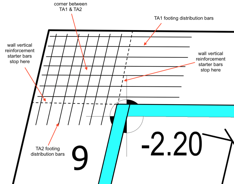
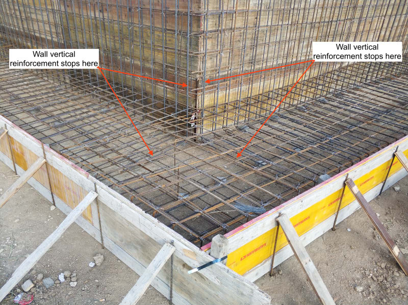
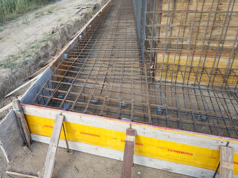
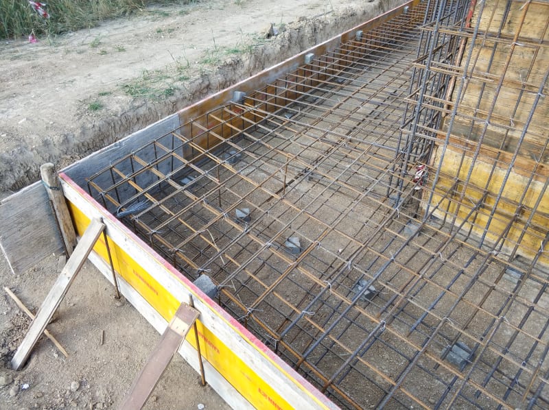
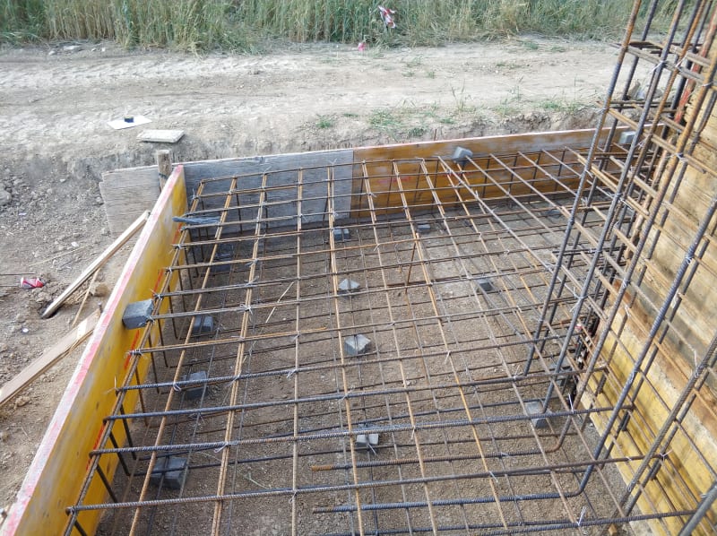
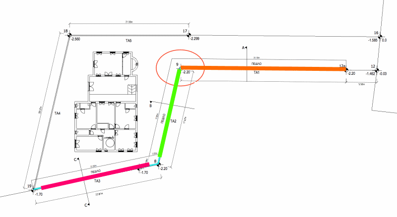
I urgently need your help regarding the distribution reinforcement of the footing at the corner between TA1 and TA2
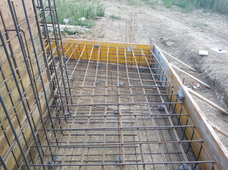
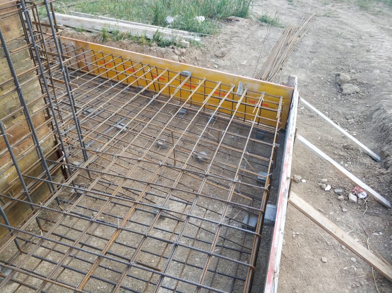
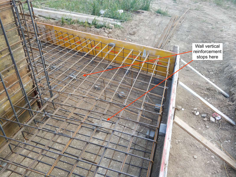
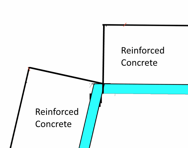
(the corner which i am referring to is shown on the drawing below, and the arrangement of the distribution bars is shown on the pictures)
Please have a close look at the reinforcement of the footing and advice if i need additional reinforcement at the specific corner.

1) As you can see from the pictures the distribution bars from TA1 footing and the distribution bars of TA2 footing extend crossing each other.
2) In addition there is no vertical reinforcement within the specified corner between TA1 and TA2

PLAN VIEW OF RETAINING WALL:

RETAINING WALL IS ILLUSTRATED WITH CYAN COLOUR

Screen_Shot_2018-03-30_at_18.37.52_is71u1.png


Reinforcement at corner between TA1 and TA2

Screen_Shot_2018-03-31_at_16.40.48_pusaox.png


PICTURES OF REINFORCEMENT AT SPECIFIC CORNER

IMG_20180330_171433_axqq09.jpg


IMG_20180330_171440_rekhay.jpg


IMG_20180330_171440_copy_utx2qd.jpg


IMG_20180330_171449_eem6if.jpg


IMG_20180330_171455_jkhz3b.jpg


IMG_20180330_171455_copy_lxshyx.jpg


IMG_20180330_171458_s9xgzi.jpg


IMG_20180330_171508_ogbfbg.jpg


IMG_20180330_171513_yuoy9b.jpg


IMG_20180330_171520_midanf.jpg
 
anyone? we are pouring next week therefore i need your advice ASAP
 
Kellez - I received your emails... take it easy. This project is in a "mess" (we will talk about that later), but there is hope.

1. I would omit all the concrete in the "interior" corner (see the image below). The wall stem stem thickness and reinforcement are minimal, the wall will deflect under soil loading. I would want each wall to move independent of the other. Fortunately, for this interior corner, the two walls will move closer together. An expansion joint between wall stems should take care of deflection.

Interior_Corner-1_w2ve5o.png


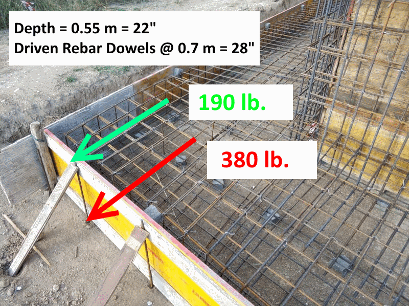
2. The concrete forming is very "neat" but, IMHO, not adequate. Assuming the slab is 0.55m thick and the driven rebar dowels are spaced 0.7m on-center, "theoretical" concrete hydrostatic force on the dowels is high (see image below). It will probably work, if the vertical concrete rate of placement is kept low... but I would not want to rely on that. On short notice, I would just put in a lot more dowels.

Forming_Support-1_uvst3s.png


3. Concerning joint in the footing - construction joints are needed. There is only so much concrete that can be placed and finished in a working day. Consider how the concrete is placed (from truck, pumped, crane/bucket, etc.), crew size / skill and don't plan on placing more concrete than should be reasonable in 9 working hours. I would split your plan into at least 3 separate placements (shown on the image below). Note: It may be possible to do 1, 2, or all 3 in one working day... if not, at least there is a logical place to stop work for the day. For a professional quality job, plan on two concrete vibrators with two independent power sources. Concrete finishing will most likely be the limiting factor... don't pour more concrete than can be finished correctly. Wet cure for 7 days, starting immediately.

Concrete_Placement-1_akwkut.png


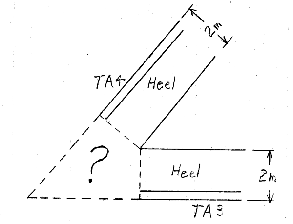
You still have to deal with exterior corner design. At the exterior corners stop concrete placement where the wall heels interfere:

Corner_Detail-1_kslj6q.png


[idea]
[r2d2]
 
Status
Not open for further replies.

Part and Inventory Search

Sponsor