Continue to Site

Eng-Tips is the largest engineering community on the Internet

Intelligent Work Forums for Engineering Professionals

  • Congratulations waross on being selected by the Eng-Tips community for having the most helpful posts in the forums last week. Way to Go!

Guidance for the Design of a Reinforced Concrete Retaining Wall 5

Status
Not open for further replies.

kellez

Civil/Environmental
Nov 5, 2011
276
Hello everyone, please find attached a drawing of the retaining wall i am designing according to EC7 together with an excel file of my calculations.
Its a cantilever L-shaped reinforced concrete wall comprised of a stem and foundation slab.

Backfill soil is well graded gravel with unitweight = 20kN/m3 and angle of friction = 25degrees (conservative value)
Wall height is 4.20m, Height of soil retained by wall is 2.70meters.
Surcharge load = 10kPa, A seismic force has also been considered.

According to my calculations my problem here is that the foundation of the wall needs to be at least 1.80meters wide in order to get a safety factor of 0.94 against sliding, which i think its too much for this design.
So for a 2.70m hight soil i get a 1.80m wide foundation slab in order to resist sliding. Dont you guys think that This is a really expensive design? am i doing something wrong? or did i get tit right?

The excel file is sectioned as follows:

0. Retaining Wall Properties
1. Gross Pressure Method
2. Eurocode Comb 1
3. Eurocode Comb 2
4. Seismic
5. Bending Reinforcement
6. Deflection (not complete)

Can you guys please have a look at my work and help figure this out? does the wall foundation need to be that wide?

[URL unfurl="true"]https://res.cloudinary.com/engineering-com/image/upload/v1514841058/tips/Retaining_Wall_Details_-_forum_lrme3i.pdf[/url]

[URL unfurl="true"]https://res.cloudinary.com/engineering-com/raw/upload/v1514841074/tips/Retaining_Wall_Design_y9vhvs.ods[/url]
 
Replies continue below

Recommended for you

SlideRuleEra said:
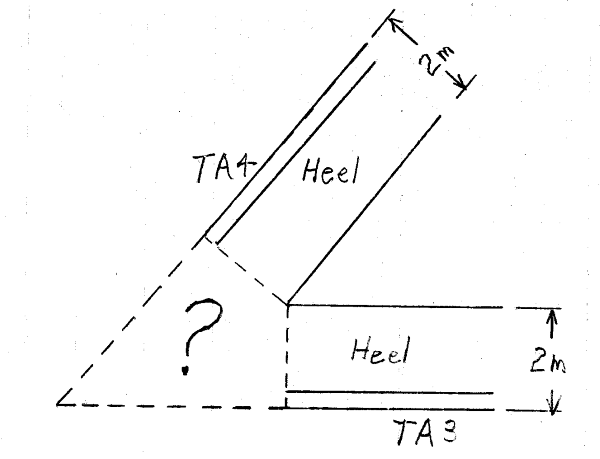
You still have to deal with exterior corner design. At the exterior corners stop concrete placement where the wall heels interfere:

Corner_Detail-1_kslj6q.png


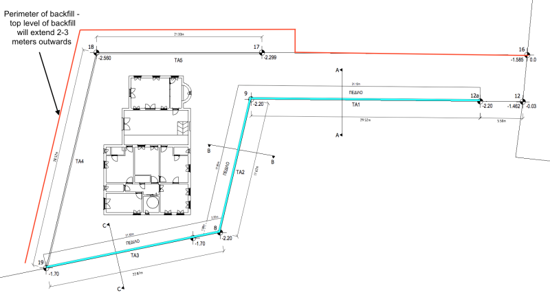
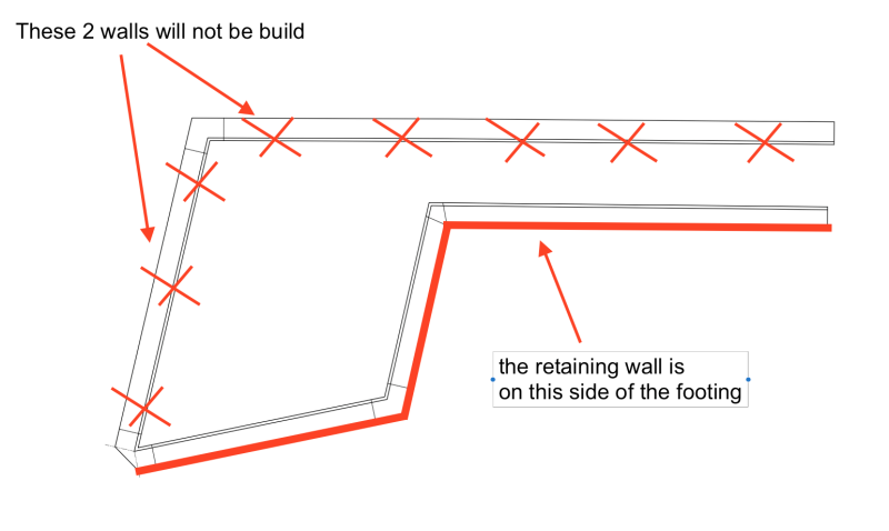
the layout of the retaining wall has been changed, wall TA4 and wall TA5 will not be build, instead we will extend
the perimeter of the backfill about 2-3 meters outwards (see drawing below). therefore the exterior corner shown on your drawing above
will not be build.

if you check the latest plan view drawing on my last post (or the drawing below) you will see that the walls TA4 and TA5 are not shown

Screen_Shot_2018-03-31_at_14.06.09_copy_pnhvc7.png
 
SlideRuleEra said:
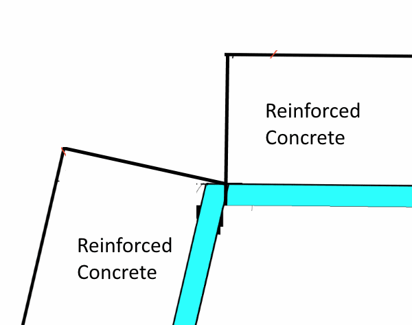
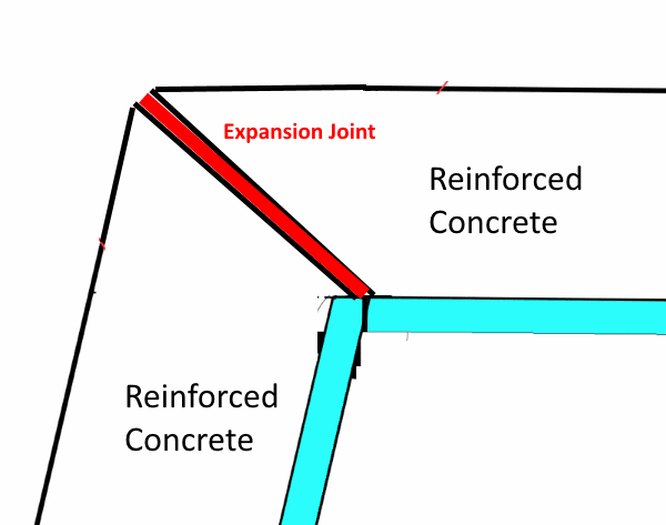
1. I would omit all the concrete in the "interior" corner (see the image below). The wall stem stem thickness and reinforcement are minimal, the wall will deflect under soil loading. I would want each wall to move independent of the other. Fortunately, for this interior corner, the two walls will move closer together. An expansion joint between wall stems should take care of deflection.

Interior_Corner-1_w2ve5o.png


Unfortunately the reinforcement and formwork of the footing at the corner shown above has already been build.

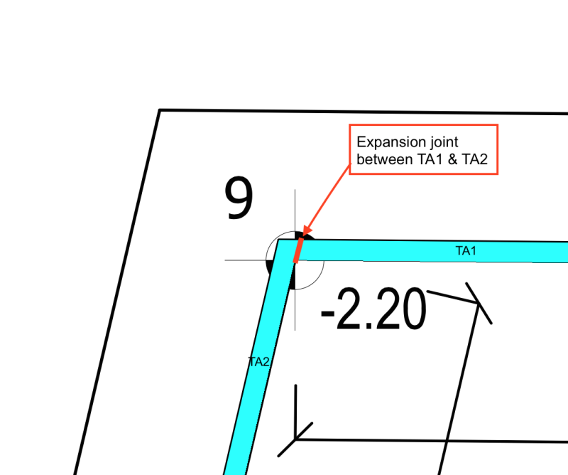
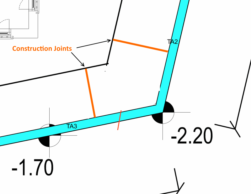
However if i add an expansion joint (as you suggested, and as shown on the drawing below) between the stem of walls
TA1 and TA2 so that the walls are independent of each other, wouldnt it still be fine? and accommodate any issues
of interaction between the two walls even if the their footings are connected at the corner?

Screen_Shot_2018-04-01_at_20.23.51_w91h1x.png
 
kellez said:
Unfortunately the reinforcement and formwork of the footing at the corner shown above has already been build.

That's what acetylene torches are for. Cut the rebar and reform... or even better, postpone the concrete placement until you complete the design. Last minute changes like that are commonplace in the heavy construction industry. I would want those two structures to be entirely separate from each other - the reinforcement was designed for one thing, and only one thing - to resist soil loading. Who knows what type loading will be applied to a single slab with two walls, each loaded in a different direction. Don't dwell on what you can't do, as I said earlier, you are in a "mess"... try to get yourself out of it.

An alternate is to do something like this:

Interior_Corner-2_singrk.png


[idea]
[r2d2]
 
SlideRuleEra said:
That's what acetylene torches are for. Cut the rebar and reform... or even better, postpone the concrete placement until you complete the design. Last minute changes like that are commonplace in the heavy construction industry. I would want those two structures to be entirely separate from each other - the reinforcement was designed for one thing, and only one thing - to resist soil loading. Who knows what type loading will be applied to a single slab with two walls, each loaded in a different direction. Don't dwell on what you can't do, as I said earlier, you are in a "mess"... try to get yourself out of it.

An alternate is to do something like this:

Ok i see your concern, I will postpone the pouring to investigate more.

Ok lets now investigate this a bit more, so your thinking is that since i have not considered something like this
in my analysis and design then i shouldnt build it like this, since i dont know how the slab will react. That is
reasonable thinking and I totally agree with you.

However from what i see you are not 100% sure on what the issue could be by connecting
the two footings together. therefore in order to be on the safe side you choose not to
connect the two footings together and build according to the analysis and design.


Now I am trying to think what could be the problem by connecting the two footings together,
it could be just fine or it could be even better as a design than by not connecting the two footings,
or there could be lots if unforeseen issues.
How can we find out? and how can we design for this specific corner if we choose to connect the two footings??

Considering the fact that my wall has been designed so that it would not slide, overturn or failure of soil
beneath, and also designed against bending and shear of the stem and footing, then what are the possible forces
that could be created at this specific corner that could be detrimental to the wall?

my wall together with the foundation is designed not to move or slide, therefore there is not going to be a lot of
stress applied to the corner reinforcement since the soil forces are already resisted by the weight of the soil
applied upon the footing.


dik said:
Can you provide joints like the attached?

the two walls indicated below in the drawing will not be build.

i think your drawing of the wall and the footings is wrong, the footing should be on the inside of
the retaining wall, therefore you should move the wall in the opposite side of the footing as shown
in the drawing below

1) what type of joints are you referring to? Expansion or contraction joints?
2) where are the joints located? on the wall, footing or both?

Screen_Shot_2018-04-01_at_22.25.19_vsyqsw.png
 
Sorry... I thought that was the soil side. You are filling the site to provide a level surface for the home?

Dik
 
kellez said:
...there could be lots if unforeseen issues. How can we find out?

Together with your Contractor, determine how many m[sup]3[/sup] concrete can be placed and/or how many m[sup]2[/sup] concrete can be finished in a 9 hour working day. The answer will determine how may linear meters of footing can be placed at one time, that is, the maximum spacing of construction joints. Depending on the answer, keeping the two walls/footings separate may be best for both design and construction. Tell us what numbers you come up with. For what it is worth, I believe reasonable construction overrules "clever" design.

Note: The 9 hour time frame is a reasonable limit on how long experienced workers can perform efficiently doing this type construction. Also, things go wrong... extra time may (will) often be needed. Start a sizeable concrete placement as early as possible in the day, even if it means waiting overnight to start.

[idea]
[r2d2]
 
1) 1st phase we are pouring only TA1 and TA2 footings, therefore only 2 footings.
the m3 of concrete are not that high.

Footing 1 is 30m x 0.55m x 1.8 = 29.7m3
Footing 2 is 18m x 0.55m x 1.90m = 18.81m3
Total = 29.7 + 18.81 = 48.51m3

lets say 55m3 in total which is 6.11 trucks of 9m3 each,
lets say 25minutes to pour each truck, total time is 3h and 45minutes


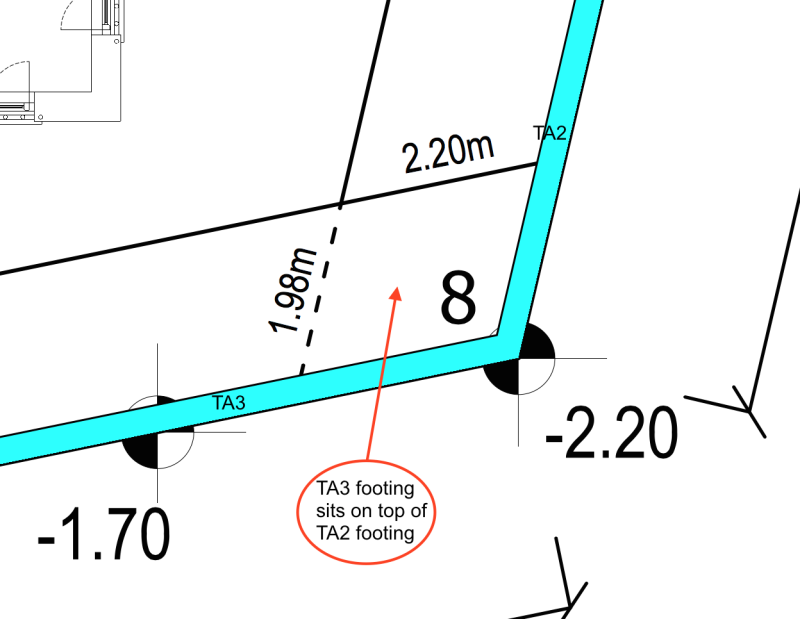
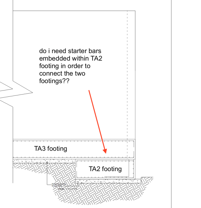
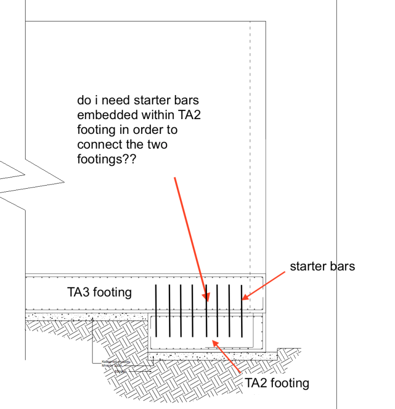
2) *we are not going to pour TA3 footing because it is on a different level than the rest of the footings,
actually part of TA3 footing sits on top of TA2 footing

see drawing below

do i need to connect the two footings together by embedding starter bars inside TA2 footing?

Screen_Shot_2018-04-01_at_23.17.24_ccrh3x.png


Screen_Shot_2018-04-01_at_23.30.16_naydrj.png


Screen_Shot_2018-04-01_at_23.30.16_glsypm.png
 
SlideRuleEra said:
Concrete finishing will most likely be the limiting factor... don't pour more concrete than can be finished correctly.

...how many m[sup]2[/sup] concrete can be finished in a 9 hour working day.

1. Placement of 55 m[sup]3[/sup] in 4 hours... plan on finishing and placement taking place at the same time.

2. Rebuild the concrete forms for full concrete hydrostatic pressure... not just the additional driven dowels I mentioned earlier. With a schedule that quick (4 hours placement) you can not risk having form trouble during placement.

[idea]
[r2d2]
 
Kellez - Review my earlier posts today. Overlapping slabs get back to the problems with loading that is not addressed in design. Consider that what you show as overlap could be a single slab (of whatever thickness is needed) that supports two short walls. This block will have to be designed for soil pressure, overturning, sliding, etc.

External_Corner-1_tzsttn.png


[idea]
[r2d2]
 
Do you need a guardrail at the top of the wall? requirements for public access (closer spaced rails)

Dik
 
Kellez - I have given this project much thought over the past 24 hours. Have even discussed it, in private, with an experienced Geotechnical Engineer who has been following the thread. You had mentioned this was a "learning" opportunity for you. Over the past 3 months, or so, I believe you have learned a lot... the proof was yesterday when faced with actually pouring concrete, you wisely decided to postpone until design / construction issues could be resolved.

The troubling part of effort to date is that the 0.55 meter thick foundation slab is the "easy" part of the project, but the Contractor is struggling to handle it (for example, under designed concrete formwork). A 3 meter+ tall stem wall is literally exponentially more challenging.

As an example of what can go wrong, picture 55 m[sup]3[/sup] of hardened reinforced concrete that is in a misshaped, useless mass. It happens, and the cleanup costs are very high.

The Contractor needs an experienced Field Construction Manager to guide him though this project. There is no way that we (Engineering Tips members) can do this over the internet. With all due respect, I don't believe you have the field experience to do this either.

I expect many members, including me, will be happy to comment on your continuing "learning" design efforts... but ONLY if it is restricted to learning, at this time.


[idea]
[r2d2]
 
Status
Not open for further replies.

Part and Inventory Search

Sponsor