Continue to Site

Eng-Tips is the largest engineering community on the Internet

Intelligent Work Forums for Engineering Professionals

  • Congratulations waross on being selected by the Eng-Tips community for having the most helpful posts in the forums last week. Way to Go!

Guidance for the Design of a Reinforced Concrete Retaining Wall 5

Status
Not open for further replies.

kellez

Civil/Environmental
Nov 5, 2011
276
Hello everyone, please find attached a drawing of the retaining wall i am designing according to EC7 together with an excel file of my calculations.
Its a cantilever L-shaped reinforced concrete wall comprised of a stem and foundation slab.

Backfill soil is well graded gravel with unitweight = 20kN/m3 and angle of friction = 25degrees (conservative value)
Wall height is 4.20m, Height of soil retained by wall is 2.70meters.
Surcharge load = 10kPa, A seismic force has also been considered.

According to my calculations my problem here is that the foundation of the wall needs to be at least 1.80meters wide in order to get a safety factor of 0.94 against sliding, which i think its too much for this design.
So for a 2.70m hight soil i get a 1.80m wide foundation slab in order to resist sliding. Dont you guys think that This is a really expensive design? am i doing something wrong? or did i get tit right?

The excel file is sectioned as follows:

0. Retaining Wall Properties
1. Gross Pressure Method
2. Eurocode Comb 1
3. Eurocode Comb 2
4. Seismic
5. Bending Reinforcement
6. Deflection (not complete)

Can you guys please have a look at my work and help figure this out? does the wall foundation need to be that wide?

[URL unfurl="true"]https://res.cloudinary.com/engineering-com/image/upload/v1514841058/tips/Retaining_Wall_Details_-_forum_lrme3i.pdf[/url]

[URL unfurl="true"]https://res.cloudinary.com/engineering-com/raw/upload/v1514841074/tips/Retaining_Wall_Design_y9vhvs.ods[/url]
 
Replies continue below

Recommended for you

SlideRuleEra said:
I'm not familiar with the Eurocodes, so can't help you on that.

Ok i will go with the eurocode factors of safety since i am designing in accordance with euroocde

SlideRuleEra said:
Have you taken steps to reduce the excessive eccentricity under "usual loading"?

Yes i did, these are my findings:

the only way to reduce the wall eccentricity (and keep the same wall shape - L) is to increase the foundation slab width to 2.10m

or by changing the shape of the wall from L to inverse T as you previously suggested, therefore i kept the width of the wall heel at 1.80m and added another 0.20m as the toe, total of 2.0m
the eccentricity now lies with in the middle 1/3 of the slab

I noticed that even if i reduced the heel of the wall at 1.60m and add a toe of 0.20m the eccentricity still lies with in the middle 1/3 of the slab

therefore now i have an inverse T-shaped wall which solves the problem of eccentricity, however i still have an issue with the resistance against sliding both in the static and seismic conditions


UPDATE:

1) Unit weight of concrete changed from 25kN/m3 to 23.60kN/m3 as you suggested
2) After calculating the surcharge load of the building in greater detail i have increased the loading from 20kN/m2 to 26.10kN/m2
3) For the design to pass I need to increase the slab width to 2.20m for the L-shaped wall (eccentricity is fine now even with the L shaped wall due to the increase in the slab width)

and

2.40m for the T-shaped wall -> 2.20m for the heel and 0.20m for the toe

Please let me know how do you want to proceed. I do have a question regarding the wall as whole and not by analysing just one meter per run, which i think will eliminate the sliding issue of one of the walls, however i will leave that one for the end once we finish designing the wall by analysing it per meter run

 
Some of the issues we covered here include

1) Properties of backfill - very important for Ka coefficient
2) Building surcharge load and how it acts on the wall
3) Factors of safety for different types of loads including seismic.
4) Unit weight of concrete changed from 25 to 23.6
5) Resolve wall eccentricity issue by changing wall shape or increase foundation size.

I think all the above are resolved but I still have an issue with the design against sliding. My thoughts are:

Now what exactly determines the resistance against sliding?

1) That would be the total weight of the wall (stem + foundation) in addition to the soil on top the heel.
2) Another parameter that determines the sliding resistance is the angle of friction of the soil underneath the foundation, i think this could be one of my issues now.

Up to now i have used an angle of friction of 28 degrees, but i dont really know what is the correct value.

Since this is an in-situ soil and not a compacted backfill is it possible that the angle of friction be very high?


kellez said:
Now what exactly determines the resistance against sliding?

Factor of Safety = Driving Forces / Resisting Forces

The value of the coefficient of friction between the concrete heel and and to soil supporting it is a major factor.
Also, cohesion of the soil can be important... but probably not on this project.

See pages 79-82 of Technical Release Number 74, "Lateral Earth Pressure", US Department of Agriculture

You may have to take steps to develop passive soil pressure on the front of the heel to assist in resisting sliding.
SlideRuleEra on 12 Jan 18 said:
...there may be compromise advantages to an excavated foundation.
 
SlideRuleEra said:
The value of the coefficient of friction between the concrete heel and and to soil supporting it is a major factor.
Also, cohesion of the soil can be important... but probably not on this project.

I will discuss this with the client and ask for some lab testing in order to determine
a) the angle of friction and b) bearing capacity of the insitu soil - underneath retaining wall
c) sieve test to determine the type of soil

Before i start making changes i have an important question

Question 1
I think i never mentioned the fact that the backfill soil will be compacted every 30cm
Isnt this going to change the angle of friction of the material?
The angle of friction of the backfill material i am currently using is 30degrees, isnt this going to increase?

Question 2
After reading the suggested pages from the document above (U.S. DEPARTMENT OF AGRICULTURE SOIL CONSERVATION SERVICE ENGINEERING) I noticed that the safety factors are not applied directly to
the forces or materials however the document suggests a minimum safety factor to be reached. I just wanted to comment on that because for me its not necessary to reach such a high FS since my
factors of safety have already been applied to the forces and materials.

Question 3
What happens to the surcharge load from the building during an earthquake? Do i simply use the same value as with the static analysis?
I just noticed that the Mononobe Okabe method doesnt actually consider any surcharge load and therefore will need to be added thats why i was getting very low force values when using this equation. for that reason i have avoided it and i am using the Seed and Whitman method

 
steve49 said:
otwithstanding that comment, is your base width actually out of proportion? You cite a 1.2m base for a 2.0m high wall as another example: B/H=0.6. Your design is 1.8m base for 2.7m height: B/H=0.67. Not too different at all. What do you know about the other wall? Did it have access to good fill, lower design surcharge, other factors in its favour?

Some textbooks (eg Bowles) give B/H from 0.5 to 0.7 as a guide. You're within that range. My own experience from looking at old retaining walls is that many show signs of movement (leaning and sliding) to the point that I'd say they were 'under-designed', so I'm not too confident in the lower end of any old rules of thumb.

The above rules of thumb give (eg Bowles) gives B/H from 0.5 to 0.7....i dont think this rule of thumb takes into consideration any surcharge loads from nearby buildings?
 
Very good dialogue for this thread... one of the better threads. A couple of construction issues... I would normally have a distance of 100mm or so from the toe of the footing to the face of the wall to rest the wall formwork on. In addition, I would batter the wall into the soil by 300 or 400mm so that with any rotation, the wall becomes more vertical.

Dik
 
Kellex - Good work from you. You seem to have a want to learn which is admirable. Well done to SRE, OG and others for providing great advice.

I have only looked at this thread in the last half hour, there is a lot to go through and i have only skimmed the replies so excuse me if this has been said already.

I think you have a bearing capacity problem. In your spreadsheet and drawing you has assumed (or calculated?) a bearing resistance of 250kPak, is this an ultimate or allowable?. I dont think a base soil with Phi' of 28 degrees will give you that. Your drawings done indicate if you are intending to bury your base or sit it on ground level? If you are not burying your base it reduces your available bearing capacity.

I did a quick and dirty check using Terzaghi's equation and for the Phi above, assuming 1.5m breadth by 1m width, you have an allowable bearing resistance of 156kPa. See below.

Capture_tr9fk1.png
 
dik said:
Very good dialogue for this thread... one of the better threads. A couple of construction issues... I would normally have a distance of 100mm or so from the toe of the footing to the face of the wall to rest the wall formwork on. In addition, I would batter the wall into the soil by 300 or 400mm so that with any rotation, the wall becomes more vertical.

Dik

Very good suggestion thanks a lot, you are absolutely correct, I need that 100mmm distance otherwise where would i support the formwork?

About battering the wall into the soil, again thats a good approach because at some point in the future you might get some rotation especially during an earthquake. i will have to talk about this with the formwork contractor and see what he says, how expensive or difficult this might be?
 
EireChch said:
Kellex - Good work from you. You seem to have a want to learn which is admirable. Well done to SRE, OG and others for providing great advice.

I have only looked at this thread in the last half hour, there is a lot to go through and i have only skimmed the replies so excuse me if this has been said already.

I think you have a bearing capacity problem. In your spreadsheet and drawing you has assumed (or calculated?) a bearing resistance of 250kPak, is this an ultimate or allowable?. I dont think a base soil with Phi' of 28 degrees will give you that. Your drawings done indicate if you are intending to bury your base or sit it on ground level? If you are not burying your base it reduces your available bearing capacity.

I did a quick and dirty check using Terzaghi's equation and for the Phi above, assuming 1.5m breadth by 1m width, you have an allowable bearing resistance of 156kPa. See below.

Thank you, i am doing my best to get it right from the first time.

This is some great information too, and it has not been said already, thanks for bringing that up. I will look into this a bit more, Maybe i will also ask for some soil tests to determine the soil bearing pressure.
 
OP:
Both forms are tilted and there is little, if any, additional cost.

Dik
 
Thanks, dik and ErieChch.

kellez said:
Question 1
I think i never mentioned the fact that the backfill soil will be compacted every 30cm
Isnt this going to change the angle of friction of the material?
The angle of friction of the backfill material i am currently using is 30degrees, isnt this going to increase?

Keep in mind that the theory (Coulomb-Rankine) being used is pretty basic. No point in trying to "fine-tune" the calculations... the the numbers may be precise, but improved accuracy is missing.

Question 2
...factors of safety have already been applied to the forces and materials.

Most of today's codes do that. I accept that as the way things are, but it obscures the physics of what actually happens as design assumptions change.

Question 3
What happens to the surcharge load from the building during an earthquake? Do i simply use the same value as with the static analysis?

Yes, treat seismic and surcharge as two, distinct loads. Of course, they can (and will) be applied at the same time. As discussed for Question 1... keep it simple.

IMHO, the single most important thing you can do is accurately determine soil properties for ALL the soil, including backfill. Our colleagues have encouraged you to do this for some time. Accurate soil properties will allow a meaningful design that can be expected to work correctly.


[idea]
[r2d2]
 
SlideRuleEra said:
Keep in mind that the theory (Coulomb-Rankine) being used is pretty basic. No point in trying to "fine-tune" the calculations... the the numbers may be precise, but improved accuracy is missing.

Ok I am keeping the angle of friction as it is

SlideRuleEra said:
Most of today's codes do that. I accept that as the way things are, but it obscures the physics of what actually happens as design assumptions change.

I am also simultaneously calculating the design problem without any codes or FoS applied - its called the gross pressure method

SlideRuleEra said:
Yes, treat seismic and surcharge as two, distinct loads. Of course, they can (and will) be applied at the same time. As discussed for Question 1... keep it simple.

Yes i have done that already

SlideRuleEra said:
IMHO, the single most important thing you can do is accurately determine soil properties for ALL the soil, including backfill. Our colleagues have encouraged you to do this for some time. Accurate soil properties will allow a meaningful design that can be expected to work correctly.

Yes thats exactly what i am planning to do now


UPDATE:

I am also designing the exact same wall but without the surcharge load of the building.
Therefore by keeping everything the same and removing the surcharge load the results i get are:

For an inverse T-shape wall the foundation slab width is = 1.60meters -> 1.50m for the heel & 0.10m for the toe

The results now seem to be reasonable and are within the rules of thumb.

I have spoken with 2 architects and 1 engineer about the wall with the surcharge load and they all think that the foundation slab i get is way to big.
I have also seen some retaining wall designs of finished projects and they look way underdesigned when compared to mine. I am really curious to see how they carry out their designs,
for this reason I will be in contact with an engineer tomorrow and hopefully he will have the time to show me his calculations and how they actually carry out their designs.
I am really curious and excited to check my calculations against his, assuming he is willing to share

 
Eurocode suggests that any variable surcharge load should not be considered as favourable when calculating the sliding and overturning resistance.
However My surcharge load is actually a permanent load and not a variable load, its actually the load from the building nearby.

I know you also did mention not to consider the surcharge load for the resistance calculation, which i did agree with you, however i did not realise that this
was meant for the variable load and not the permanent load.

So do you think i should also consider the permanent surcharge load when calculating the resistance against sliding and overturning?
 
That is going to be a judgement decision... but you should make an informed decision. Do a sensitivity analysis:

For "usual loading" (or its' Eurocode equivalent) what is the eccentricity, and is it acceptable when the surcharge is ignored in resistance calculations?

For "usual loading" what is the eccentricity, and is it acceptable when the surcharge is included in resistance calculations?

[idea]
[r2d2]
 
kellez said:
So do you think i should also consider the permanent surcharge load when calculating the resistance against sliding and overturning?

Is the building on your property? I would not consider it. I would look to do other this first increase heal width etc.

Kellez said:
EUROCODE suggests a factor of safety of 1.35, this is what i used up to now

From one of the earlier posts you said the above which isnt correct. Eurocode works on the basis that the Ed < Er. Your design action effect (Ed) should be less that a design resistance (Er). Design means factored so the factors are already built in.

Good work.
 
After further checking my calculations i finally got my design of the foundation slab at a width of 2.0m which is final


Now i am designing the vertical reinforcement for the stem of the wall.


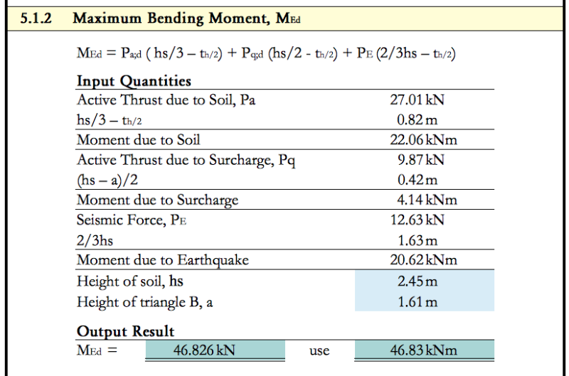
1. the maximum bending moment i get at the bottom of the wall were it connects with the foundations is as shown below

Screen_Shot_2018-02-20_at_20.32.27_cijbja.png


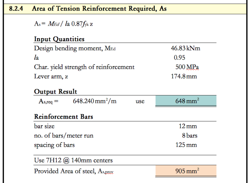
2. I then design the reinforcement required according to above bending moment

Screen_Shot_2018-02-20_at_20.36.11_vxnfmk.png


This is for the tension side of the wall, common practise suggests that the same amount of reinforcement is used on the compression
side as well, however i am skeptical about that. Is the steel on the compression side of the wall actually work?
can i save some steel by using 10mm bars on the compressions side instead of 12mm?
 
You are still working on this wall?!

Must be a good budget.
 
To answer your question, technically the compression side does not require it's own layer of steel. I've been keen to omit it when possible to keep congestion to a minimum at the wall to footing connection.
 
kellez - 12mm bars with 125mm (or even 140mm) spacing? Why so "small" and close together?

For a wall of these proportions, look into saving money (reduced rebar handling/installation cost) by using fewer bars, of a larger size with greater spacing to get the same weight of rebar / meter of wall length. Rebar sizing/spacing is a compromise, don't want individual bars to be so "heavy" that a crane is needed to place them. Also, don't want the spacing to be "too large"... but bar spacing somewhat > 140mm should not be "too large" for this wall.

Agree with jayrod12 about the compression side rebar. The Eurocode (that I am not familiar with) may have guidance on the compression side (or total amount) of rebar required.

[idea]
[r2d2]
 
Status
Not open for further replies.

Part and Inventory Search

Sponsor