Continue to Site

Eng-Tips is the largest engineering community on the Internet

Intelligent Work Forums for Engineering Professionals

  • Congratulations waross on being selected by the Eng-Tips community for having the most helpful posts in the forums last week. Way to Go!

Hard Rock Hotel under construction in New Orleans collapses... 119

Status
Not open for further replies.
Winelady,
The deck is not spanning in the direction shown on the plans...its spanning in the other direction driving all the load to the perimeter W10x19...Try W10x19 spanning 25'-9" with 24' of trib.
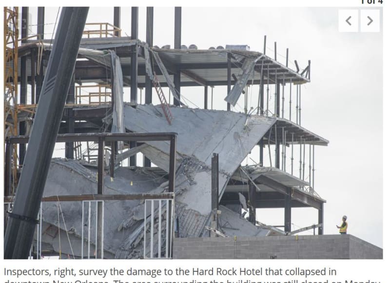
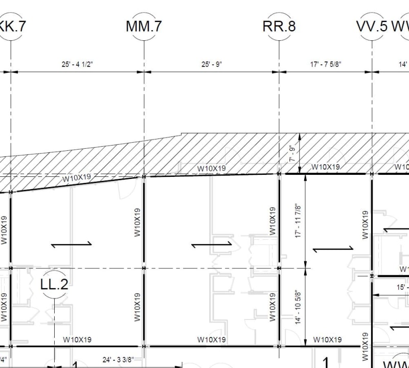
deck_orientation_dgonpk.jpg


deck_orientation_2_btfizl.jpg
 
That's uh, WinelandV (not a Y)...

At any rate, that's a pretty big change from the plans, or it's a pretty massive miss by the contractor.
 
IceNine/Winelandv: yeah table 3.6 wouldn't apply to the composite phase D+L but it can be used in the pre-composite phase and 51 psf is about the self weight of the deck listed in my Vulcraft catalog. As already stated though it may be likely that these were place holder beams in the drafting and got corrected in later set.

structuralengr89:
Edit: I believe you are correct for the lower levels,Roof level doesn't appear to have a deck span callout. The area in the plan screenshot in your post appears to be the collapsed deck which looks to have the ribs in the same direction as on the plan though.

Open Source Structural Applications:
 
Has anyone noticed that the tables for beam to column connections on sheet S3.14 don't show column sizes smaller than W10x49. I wonder what is going on with the W10x19 beam to W6x20 column connections? Everything else seems to be called out in the tables. I also don't see any beams listed as smaller than W12x26. Maybe this was left to the fabricator's engineer to design connections? Notes on S1.0A seem to indicate delegated connection design.
 
Celt83 said:
IceNine/Winelandv: yeah table 3.6 wouldn't apply to the composite phase D+L but it can be used in the pre-composite phase and 51 psf is about the self weight of the deck listed in my Vulcraft catalog. As already stated they it may be likely that these were place holder beams in the drafting and got corrected in later set.

Unless this was meant to be a shored composite design. In the video posted above, the contractors are removing shores.
 
Strucutral89: the decking orientation changes direction in plan in places, including at corners.
 
deck_orientation_flrpyw.jpg


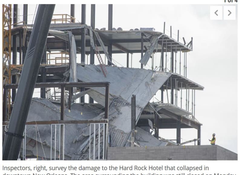
I hope the guy in the yellow vest in the lower right hand corner is getting paid well to stand in that location.
 
Yeah, he's definitely standing bow-legged
 
If the allegation in the article is true that the safety issue was raised by workers but dismissed by someone in a management/oversight position, that's almost worse than a design error. I really hope it didn't play out like that.

That video from the worker is truly chilling. Honestly harder to watch than the video of the actual collapse. It's evident the man in the video understood the imminent peril of the situation, you could hear it in his voice. The way he trailed off and said almost solemnly, "Muy grave, Papa" at the end is just so haunting. It sounded like a man resigned to fate with no recourse for his concerns.
 
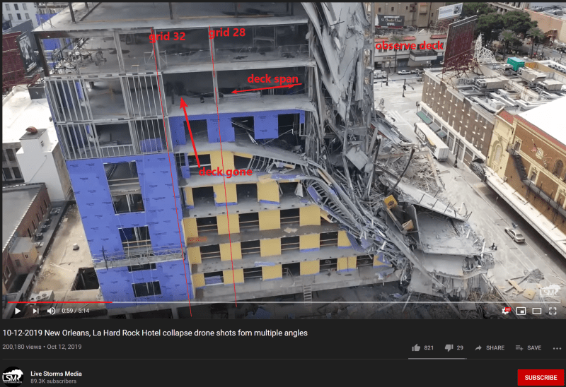
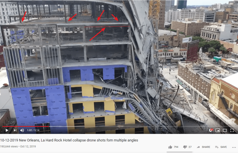
Have a look at this video around 1:00-1:05. Granted, there is now a tremendous load on those columns due to the 2 floors of slab still hanging off the right side. But good heavens look at the deflection of that beam with the two columns on top. Furthermore, observe how the deck on the 14th floor is just totally gutted all the way back to grid 32.

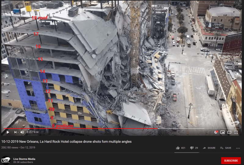
Also tagged up some numbers on the floors. The 'transfer floor' is the 16th floor. Using the elevator frame elevations as reference. Speaking of which, what happened to all the braced frames? I see none in the pics and vids? Nixed in later revision?


Deck rippage:
north_side_deck_and_grids_vpcvzm.png


Floor count:
north_side_floor_count2_djrlcl.png


Transfer 'girder' deflection:
north_side_deflection_zx4dww.png
 
dold said:
Speaking of which, what happened to all the braced frames? I see none in the pics and vids? Nixed in later revision?

I've been thinking about that, too. It seems like a major design change to go from the steel frames for the elevator towers on Dwg S3-10 to the concrete as shown in photos such as this one.

Crane_opening_-_parking_level_hlw3q4.jpg


The photo also shows the crane placed in an opening in one of the parking levels. I am looking for a photo of the crane opening at one the upper levels, but I haven't found one yet.

Crane_opening_-_a_lower_parking_level_scv9sc.jpg
 
Many good lessons for Engineers on this failure:

1. Designated Connection Design. Do you designate others to design the connections on your projects? Guess what, if it fails you will be sued. In fact, everyone on the project team gets sued - architect, contractor, structural, electrical, landscape arch...if you have insurance you are getting sued.

2. Requiring the Contractor to shore your beams. I checked some of the W10x19 in Ram Structure Composite..and the EOR must have used shored beam design. Are you relying on the Contractor to shore your red iron during construction? No way I would allow this.

3. Having beams with proper span to depth ratios. I would never use a W10 for a girder. The fly over video shows some remaining with 2 bolt double angle connections. After the flanges are coped, how much web do you have left? And then you leave that to someone else to design?

My guess for the failure was excessive deflection for both red iron and decking as witnessed by the immigrant worker's video...additional dead load that was not accounted for...followed by ripping of connection.


NOLAscience said:
I've been thinking about that, too. It seems like a major design change to go from the steel frames for the elevator towers on Dwg S3-10 to the concrete as shown in photos such as this one.

The drawings show concrete shear walls below level 8 and steel braced frames above level 8.
It appears they switched to moment frames rather than braced frames.
 
I have a couple of comments about the shoring.

1. In the construction worker's video, it shows a shore post that is buckled and tight to the composite deck. Typically, you would expect that the shore post would have a distribution beam that would provide support to all of the low ribs of the deck, and not just a single point. Now, I guess this could be re-shoring, and a post is located directly above, but that does not make sense from a construction sequencing. Since this is composite deck, there is no need to strip forms. It would make no sense to remove the beams, from a labor perspective.

2. I worked as a laborer for a GC while in college. While we did not do anything of this scale, we did do a few suspended slabs with shored construction. Once the concrete had cured, and it was time to removed the forming and shoring, we would do it in a very methodical method. We would lower the shoring by turning the screw jack 1/4 turn at a time on all of the shore posts, so that we would let the permanent structure pick up the load slowly and more uniformly. This also would prevent accidental stress reversals and large point loads. In watching the video and reading the interpretations, it appears (one cannot be sure) that the method was to remove posts completely. If this is the case, you could get all sorts of bizarre stresses, especially in a structure that appears to be as flexible as this one.

I still have numerous questions and concerns on the structural design, but shoring design and installation needs to be examined closely as well. One would think, that on a project of this scale, shoring design submittals would have been submitted to for review by the SEOR. This would be especially important if the design was to utilize shored composite construction.

 
Yeah that buckled post is odd. It looks abandoned. I’ve seen that happen when props buckle. The contractors bail and raise the alarm.
 
NOLA, those are still the PT levels. PT from foundation to level 8 which was the 36" transfer slab. The steel framed cores above were a mix of braces and moment frames according to the 6.8.2018 drawings, starting at level 8.

On a similar note. I wonder if they actually used the 'typical column to embed detail' on s3.13 for the corewall (frame) columns.

And speaking of embeds, S2.19 - are these supposed to be moment connections? If so, why? To give fixity and reduce beam sizes? Surely not for any sort of lateral stability since these are at mezzanine level, even though I dont see any w18x35 or w24x55 on the mezz plan. Maybe some more insight on the "yea there are typos, we'll go fix them later" situation? Not sure I understand the welding scheme on these connections either. Also I'm really digging how every detail that shows a headed stud calls for 3/16 all around fillet, yet the gen notes for steel deck state that studs are to be gun welded and mentions ferrules, etc. So, whoever wrote the notes at least knew the basics of headed studs. Granted, I'm not the biggest fan of stud gun welds - I've witnessed studs literally fall off of embeds when i was moving them out of the crates on site one time. The entire batch. Drop an embed on the dirt and PING, down to 3 studs. But...imagine the fab time for the 5k embeds
 
What type of collapse would this be officially referred to as?
I'm used to seeing damage from collapses caused by external forces such as natural disasters. But seeing these 'seemingly' random collapses like the pedestrian bridge at the Florida university is quite disturbing.
 
Status
Not open for further replies.

Part and Inventory Search

Sponsor