Eng-Tips is the largest engineering community on the Internet

Intelligent Work Forums for Engineering Professionals

  • Congratulations waross on being selected by the Tek-Tips community for having the most helpful posts in the forums last week. Way to Go!

Hard Rock Hotel under construction in New Orleans collapses... 119

Status
Not open for further replies.
I'm new to this forum and learning a great deal from the structural discussions. It is my experience that collapses like these are usually construction accidents caused by a sequence of events. Hard to analyze because the load or stress is no longer present. Does anyone know if there were operators in the cranes at the time of the collapse?
 
IceNine,

I stand corrected. I see the steel crossing between 10 and 11 and I do need new glasses which I will get this week.

With regards to the crane coming up again, just because an idea is old does not mean it is bad. The constant pounding of steel deck
with or without wind is a factor that should be considered.

Regards,
 
TGHAN said:
Does anyone know if there were operators in the cranes at the time of the collapse?

Someone -- either on this forum or on a YouTube channel that has been discussing this collapse in detail (I won't say 'analyzing' because the guy knows nothing about structural engineering, steel design, or concrete design) -- said that they saw the crane operator scrambling down the ladder to the roof level. I haven't been able to see this on numerous viewings of the collapse video. The Iberville St crane was holding a rather small steel beam that was being attached to a mechanical room on the roof level at the time of the collapse. The other crane did not seem to be in operation at the time of the collapse -- at least it wasn't connected to a lift load in the videos after the collapse.

Best I can tell, the crane operators have not talked to the media. OSHA has certainly talked to them, so again, the OSHA report should be enlightening.

We found out last weekend from the wife of one of the deceased that he died on the 7th floor, which surprised me because all images seem to show that the parking garage up to the 8th floor podium slab seemed to fare well, even with the building above dropped on the 8th floor podium. Speculation is that he may have died when one of the post-tensioned cables failed. But perhaps he was on the 7th floor, near an outer wall (he was a plasterer) and was killed by tumbling debris and the post-tensioning is fine. I guess we will find out when OSHA makes its report in 6 months or so. EDIT: Part of the 7th floor extends beyond the extents of the 8th floor, so this area is where he might have been.

Referring to a second victim (from an article yesterday in The Advocate, NOLA.com), "Wimberly’s body is under rubble on a section of the 11th-floor near North Rampart Street, but crews have been unable to retrieve it."

I'm wondering if the concrete in the upper decks met the specs, especially with regards to maximum aggregate size. In some photos, you can see rocks the size of a quarter, probably, in a 5 1/2" thick deck (as most are in this building). This might affect bonds strength with the rebar crossing the center corridor of this building.

The change is direction of the decking may have also contributed to the collapse, both in the 'corridor' and the cantilvers. This EOR and contractor have built 2- and 3-story buildings with this sort of decking on the overhang, but maybe the effects of more floors, plus shoring and column offsets, combined to create the collapse.

So far, we have only seen the structural permit drawings, from more than a year before the collapse, but there were revised architectural drawings from just a few months prior. So, there may be a newer set of structural drawings. I think it is suspect that many engineers here, even those with experience in high rise design, have viewed the permit set, yet most here are still mostly confused by the design. A design should make sense to professionals, shouldn't it? Again, maybe a better set exists.

 
New drone image of the building.
103019_hmos35.jpg
 
We have found what may be the cause of the collapse!

I apologize in advance if this post seems disorganized, as it was cobbled together from a few different discussions.

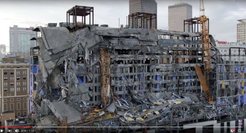
Today I watched this video, "HARD ROCK COLLAPSE ULTIMATE LOAD PATH FAILURE 15TH..." Watch that video at about 30:40 to see the initiation of collapse in the area of the curved Rampart St side of the building. (I love this 'new' pool view of the start of failure that came out last week. I kept wondering when we would see security camera footage.) The rest of the video discusses the location of failure in non-technical language.

Someone shared this excellent analysis of the loading and framing at the 15th Floor privately with the person who produced that video:
In commentary for that video, a user named Bobby posted this 3D view of the framing above the 13th Floor that is very helpful:

I had tried to sort out this framing, but I just didn't have the patience for it. There are so many different column lines and rows. As on the first link above, it's obvious that on the Rampart St side, the columns at the 15th Floor do not line up to directly support the columns from the 16th floor. It's also pretty obvious that the beams at the 15th floor are not big enough to act effectively as girders to support the loads from the 16th Floor, 17th Floor, and the "Roof". (I couldn't easily find the dimension from Col Line HH to JJ on the 15th Framing Plan, so I gave up and made a reasonable assumption.) There is so much variation in the column lines and spans that it seems that each and every beam would have to be evaluated separately. (In the days of hand calculations, we would have made the spans and framing more uniform.)

As a start, I checked one beam on the 15th Floor, the beam between BB & JJ at Col Row 10.2. The following is what I found.
(Note that it's possible that the beams in Col Row BB and JJ are worse than the beam from BB-JJ, but I didn't have time to check that yet.)

My findings and assumptions are:
(1) Did NOT analyze as composite concrete and steel beams, as MOJOJOHN says the studs are inadequate for composite action.

By the way, these beams are not composite steel beams. I checked a few and found that the studs were not
sufficient for composite action. They merely attach the slabs through the deck to the beams.

(2) I looked at the loading on the W16x26, loaded at approximately 10'-6" from Col Row JJ, with loads from Floors 16, 17, and Roof above via the column I will call "FF.1"
(3) At Floor 16 (and 17) in Col Row FF.1, the W10x19 carries the floor load of concrete and steel decking (assumed 45 psf and 53 psf, respectively, may be off by a few pounds) plus the design live load of 40 psf (no live load reduction). These beams frame into the Column FF.1. These beams carry almost 2000 lbs per foot from spans that are 27'-9 1/2" and 26'-2 7/8", for a total of 3862 lb/ft. Assumed that construction materials in place on October 12th are approximately equal to design loads, or that the floors would have eventually seen AT LEAST these design loads.
(4) The column FF.1 at Row 10.2 carries a total design load of 60.6 k from Floor 16, 60.6 k from Floor 17, and 52.1 k from the "Roof" for a total of 173.3k.
(5) With the 40 psf applied load on the 16th Floor & 17th Floor and 20 psf for the roof (I remember seeing a higher design load for at least parts of the roof, but I cannot find that information today; in any case, this was a part of the roof that was blocked off from guests' use), the W16x26 has the following Critical Stress Ratios:
Bending 1.342
Combined Bending 1.477
Shear 1.855

I haven't checked the bolts for this beam's connections yet.

This would indicate that the poor W16x26 will fail in shear, though as I mentioned above, the connection of the beam in Col Row BB at the Rampart St facade, also a W16x26, almost certainly failed first, as it carries load from TWO of these W16s.

Of course, we still have to say, "This was only the Permit Set. The For Construction drawings in use may have been revised", but I think the area identified is the initiation of failure for this building.

I can scan and send my sketches and notes for this analysis later. I suppose it's only fair to redo these calculations with the appropriate Live Load Reduction, but I don't have time to do that now.

What do you guys think?
 
I've always thought these transfer beams were the root of the problem.
See my post on 16 Oct 19 20:06.

 
As pointed out by dold (16 Oct 19 22:40), it appears the transfer beams are actually at level 16, not 15.
 
NOLAscience - I don't think you can assume the full 40 psf LL when looking at collapse, we don't know what actual load was on the beam but if it fails on the DL then that would be a strong indicator of the cause (maybe one of many).

Building on what you have in your post I looked back at the connections in the permit set. The permit sets notes delegated design except where designed in the drawing set. The drawing set shows all shear plate style (S3.14), I recall seeing some pictures showing a shear plate so I assume this was the style used.

Looking at S3.14 for W16x26 shows a 4 bolt (3/4" A325) with 1/2x4 plate and 3/16" weld. ASIC 14th page 10-110 for this configuration doesn't show a load for STD hole 1/2" plate but SSLT 41.5 kip but weld is 5/16" - drawing shows only 3/16" weld. 3/16" weld is only shown for 1/4" plate where connection capacity is 34.8 kip. So actual connection capacity is somewhere between 41.5 and 34.8 kip - ASSUMING actual connections followed permit set Typical.

If I take your 173.3 kip column load and multiply by 0.6 (rough estimate of DL only) that is 104 kip, assume 1/2 to each end of the W16 is 52 kips. Connection at best 41.5 - so connection failure. A connection failure also explains the sudden collapses. A beam overloaded would probably deflect a lot and then yielded instead of suddenly fracturing. Where a connection would tend to fail suddenly as bolts ripped out, weld broke or some other failure mode.

*** Edit ***
I saw a YouTube video showing a beam with two rows of bolts. I assume it was an extended shear plate connection so at least that connection was different than the permit set connections I discuss above. It would be nice to see the final shop drawing set but at this time my evaluation above may or may not be an accurate description of the actual connection.

 
I gave up on running numbers based on the permit set of drawings since the photos show many differences between the drawings and actual construction.
The slabs seem to be thicker than the 5.5" shown on the drawings, and the transfer beams appear to be supporting one additional floor and the roof as opposed to two additional floors and the roof.

I do think the transfer beams/connections are the problem, but we probably can't run the actual numbers based on the information we have.
 
He replaced it with this one, which has a couple of corrections, but still some errors I need to point out to him:

Unfortunately, because he made yesterday's video private, we have also lost most of the comments from that video. I have a few screenshots, without the hidden replies.

Due to the transfer framing being at the 16th Floor, not the 15th floor (but, note that the roof load I am using is quite low compared to the load from the added enclosed rooftop bar), revise the Total point load from 173.3k to 112.7 k (DL 84.0k), and reactions to Rleft = 47.7k, Rright = 65.0k.

I see the Shear Stress Ratio as 1.209 with V)allow = 54.0k. Again, that is with the Design Live Loads.

DL is 77% of the total load in my (original) 2 floor and roof loading; it is 74.5% for the (corrected) 1 floor and roof loading. Compare my DL only beam reaction of 48.4k to ldeem's calculated connection capacity of between 41.5 and 34.8k.

Remember, this isn't even the worst beam/girder AND we don't know if the beams were revised at the same time that the newer set of architectural drawings were released (May 2019). If I were sure these were the beams used, I would calculate the reactions for the worst beam/girder in Col Row BB. I think IceNine is correct, we have to get the FINAL For Construction set.
 
NOLAscience
Do you have a link to the security camera footage that you refer to?
Re: "I kept wondering when we would see security camera footage."
 
GPR_Tech said:
NOLAscience
Do you have a link to the security camera footage that you refer to?
Re: "I kept wondering when we would see security camera footage."

Here it is:

He went back and played the first indications of the floors falling (at least two, following the same pattern) in the now "private" video. Go to 7:30 in the video, then press the "." key on your keyboard and keep tapping it until you start to see the failure. The "," button plays the video back, frame-by-frame.

This video was taken by a security guard or similar person in a nearby hotel of the playback of the security camera footage using his/her smartphone, so that's why there is a bit of jiggle to the image.
 
After watching some YouTube videos showing double row of bolts on a connection I have to correct my earlier post. The permit plan connections do not seem to be the standard connection used in the final design.
 
Re: "A news item about concrete strength vs. removal of temporary shores at the hotel"

I'm not saying that the temporary shoring should have been removed when it was in this case.
But, what the headline failed to mention is that temporary shoring or formwork may be removed based on concrete strength testing and Engineering approval. In my experience this is the common practice.
 
Does not sound like it matters anyway. This structure appears to be an engineering disaster. The shoring removal simply expedited the process.
 
GPR Tech,
GPR Tech said:
But, not mentioned in this article is that temporary shoring or form work may be removed based on concrete strength testing and Engineering approval. In my experience this is the common practice.

In the article it states:
[blue]Usually, when post shores can safely be removed depends on testing of the concrete in a lab, which measures how much pressure is required to break it. The tests are to be run three days, seven days and 28 days after concrete is poured.[/blue]

 
Status
Not open for further replies.
Back
Top