Continue to Site

Eng-Tips is the largest engineering community on the Internet

Intelligent Work Forums for Engineering Professionals

  • Congratulations KootK on being selected by the Eng-Tips community for having the most helpful posts in the forums last week. Way to Go!

Help me understand this roof framing

Status
Not open for further replies.

SinStrucEng

Structural
Nov 11, 2022
66
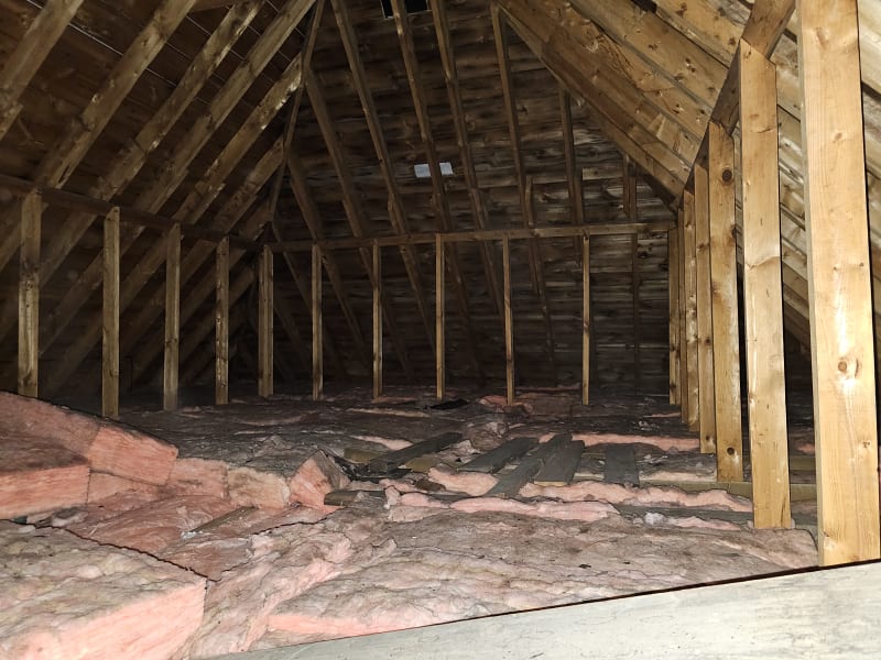
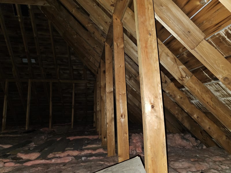
We have a rafter framed roof with a ridge plate (rather than ridge beam). There are few collar ties, but the rafter ties (which act as the ceiling joists) span in the direction opposite of what I would expect (they are perpendicular to the collar ties and parallel with ridge). There is a knee wall at around 1/2 span of the rafters, which simply sits on the ceiling joists below.

What is stopping the exterior walls from splaying out? Exterior facade is brick and in great shape. Structure is from the 1970s. We were hired to design a new staircase/opening into the attic so that the space can be used for storage and whatnot.

My intention is to cut the existing ceiling joists back a touch (36" or so) from the CMU firewall to fit a staircase from the second floor and to simultaneously upgrade the joists (either sister or replace with new of a different size) to make them adequate to support the expected dead/live loads. Current ceiling joists are only 2x6 at 16" so they will become either 2-2x6 at the least or maybe 2x8, 2x10, etc (this analysis isn't complete yet).

My main worry originally was that by cutting or removing the ceiling joists, you'd compromise the roof. But it appears that these joists are literally only supporting the ceiling and insulation, and don't tie the roof together at all... They're even lapped over interior partition walls. What am I missing? Is this roof magic? We live in a heavy snow area too.
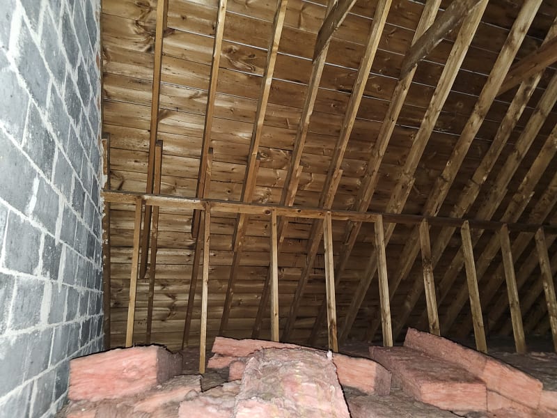
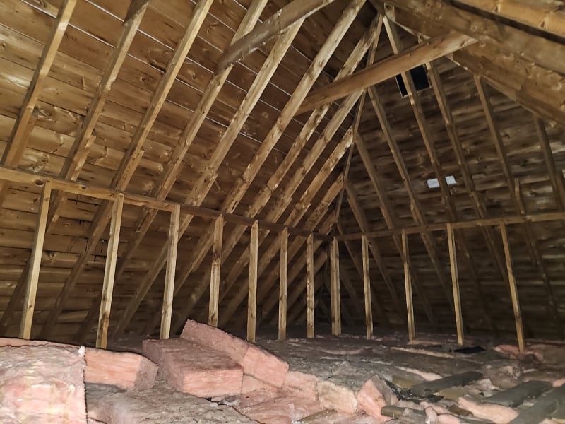
20240607_091307_vogiz3.jpg
20240607_091304_x2cjl6.jpg
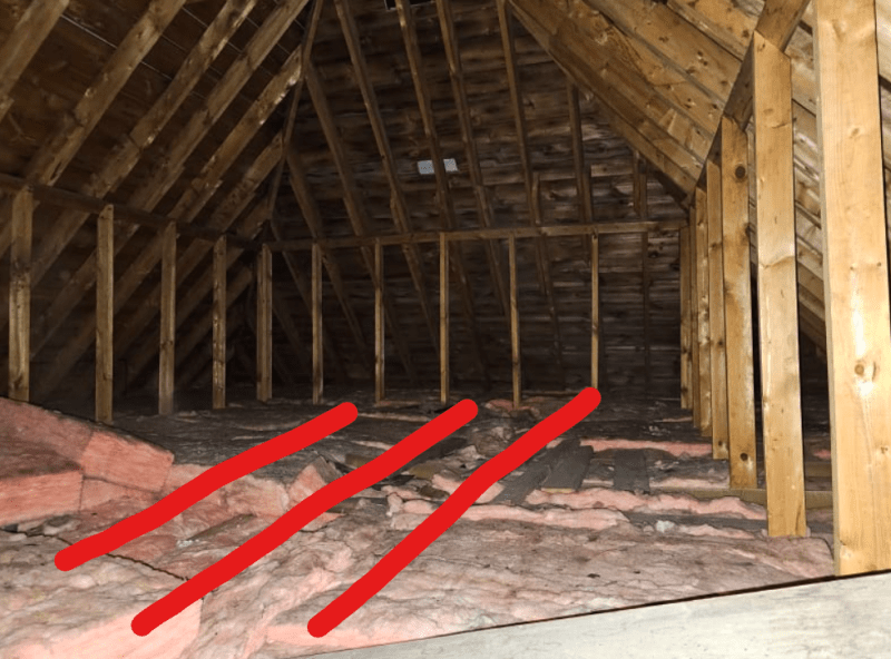
20240607_091315_rr8svt.jpg
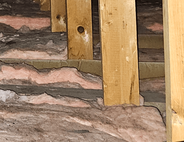
20240607_091311_drbqhg.jpg
 
Replies continue below

Recommended for you

The knee walls provide vertical support for the rafters. The thrust from the rafters is taken out at the ceiling joist level. lapped ceiling joists is common.
 
Thanks @jayrod12, but wouldn't the ceiling joists need to be perpendicular to the ridge in that case? In this case they are parallel with the ridge. How would they resist the thrust if they span in the other direction? See snippet below for ceiling joist orientation.

Screenshot_2024-06-19_102439_cvttsp.png
 
It looks like some of the ceiling joists are running the other way, at least where that right-side knee wall is, but if none of it is really attached to anything then roof magic indeed. The interior walls below may be helping keep the exterior walls from splaying. That roof pitch looks relatively steep, so the thrust isn't as bad. Adding the stair opening and reinforcing the ceiling joists is your chance to improve it.
 
Thanks @RPGs. I personally spent 30 minutes in that sweltering attic trying to figure it out. None of the ceiling joists go in the right orientation, even at the right-side knee wall that you mentioned. That "wood" looking thing is actually just old tubing/venting.
 
I wouldn't be shocked if the ceiling finish is providing a bit of diaphragm type action. Lath and plaster, or gyp board, ceiling finishes would likely provide enough capacity.
 
There are boards laying up there, I suppose to walk on.
For these to have any support the joists would need to run 90deg to your red lines.
Go up with a head lamp, camera, and rake, and poke around some more.
The joists may not all run the same direction.

= = = = = = = = = = = = = = = = = = = =
P.E. Metallurgy, consulting work welcomed
 
Everything holds up a roof together in these cases as mentioned above (steep slope, knee walls, sheathing, sheetrock ceiling, even siding and paint). I find it somewhat rare to see major thrust issues at the top of walls in finished houses because of all this extra stuff holding it together (aka roof magic as RPG said). Usually issues show during construction before any redundancy is built into the system.
 
@EdStainless, those boards are laying on batt insulation and run in the same direction as the ceiling joists. I've checked the entire space. Those boards are not supported, they were literally just thrown in there and are floating.
 
so the things that I see in the lower right corner of that picture are not the edges of joists.
It sure looks like wood at the bottom of each of the knee wall posts.

= = = = = = = = = = = = = = = = = = = =
P.E. Metallurgy, consulting work welcomed
 
I 100% agree that it looks like wood but it's not. As mentioned above it's a felt-like tubing. See picture below. The "wood" has wrinkles. The knee walls on the left and right are actually sitting on a single ceiling joist (not even doubled). There is another plank of wood that is in the frame, but again, it's just a loose piece of lumber.

Felt_ar0omb.png
 
That looks like a 1940s roof. The engineering calculations on this are going to be really unfriendly to any kind of modification.
 
Since the roof slope is steep, I suspect there's a lot of diaphragm action going no. It would transfer some of the load to the corners.

Throw in some luck, and I'd guess that's why it's still standing.
 
During your upfit, I would tie all the rafters to the new floor sheathing using some 2 x 4 struts.
I run into this frequently in older homes where they want to do an attic upfit.
I have kinda of tried to stay away from these at this point in my career as they are a pain in the ass and then getting the load down into the crawlspace/basement through a few stories is challenging.
 
Thanks everyone. I decided to keep the existing 2x6 at 16" ceiling joists in place and have the contractor provide new 2x10 joists at 16" for the new loads.

The original 2x6 joists will only be carrying the gypsum board ceiling for the floor below, whereas the new joists will be there to carry the expected live and dead loads. The new joists will span in the same direction and will be lapped at the same locations as the existing ones. I am not touching the roof at all so as to not affect the "magic", lol.
 
If you happen to be adding sheetrock and insulation, you are touching it.
 
Fair point XR250, I meant that we are not modifying the framing in any way.
 
If you're cutting a hole in the ceiling you are.

There's no magic in this. It's all physics. There's a load and it's being resisted. It's your job to figure it out and ensure it can still(?) resist the design loads after your work is complete.
 
phamENG, I am referring to the roof rafters. Otherwise, yes, we are obviously cutting back some ceiling joists to make space for a new opening. As shown above those joists aren't working as rafter ties anyways. With the added floor sheathing for the joists (which there is none currently), gypsum board on the rafters (there is none currently), diaphragm action would be improved. The goal is to improve on the structure as much as possible without breaking the client's budget while also meeting their desired goals.

Sorry for making a joke about the "magic", tough crowd.
 
How does the tension transfer between sheets of plywood?
 
Status
Not open for further replies.

Part and Inventory Search

Sponsor