Continue to Site

Eng-Tips is the largest engineering community on the Internet

Intelligent Work Forums for Engineering Professionals

  • Congratulations cowski on being selected by the Eng-Tips community for having the most helpful posts in the forums last week. Way to Go!

Hole to hole distance & inspection, ASME 14.5

Status
Not open for further replies.

Bguarino

Mechanical
Sep 3, 2019
2
I have a drawing that references ASME 14.5 for interpretation. On this drawing is shown 4 holes that form a "square" shape, and dotted lines connect the 4 holes. There is one dimension for the width and one for the height.
Untitled_qjupib.png


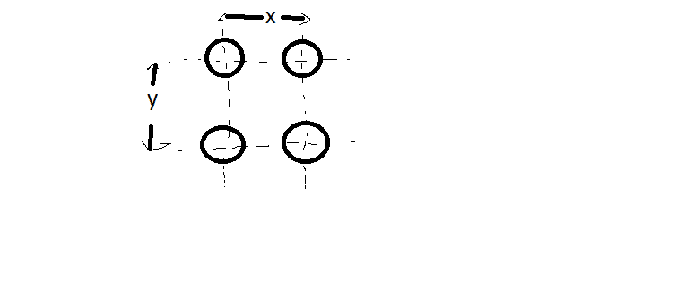
How many measurements should an inspector record? The engineer who created the drawing says there should be 4 measurements because of the dotted lines. However in ASME 14.5 it states that patterns should be clearly marked with "nX" (or similiar). He says the dotted lines indicate the dimensions extend across to the other holes meaning they need to be inspected as well, and is refusing to place a 2X in front of the dimensions.

I do not believe the intent is clear. And side note- I also do not think dimensioning it this way ensures the holes are in the correct positions nor aligned at 90 degrees to each other. GD&T should be used?

What is correct?
 
Replies continue below

Recommended for you

He doesn't need to add "2X" in front of the locating dimensions, the mutual basic location is implied (I hope the X and Y dimensions are basic). See the attached example from Y14.5-2009.

20190903_135716_eh5snc.jpg
 
Y14.5 makes no mention of how or how many features should be inspected. This is an age old debate - typically from a design standpoint we say every feature should be inspected (though some people have varying opinions on that). If the designer is okay with or wants to specify something else, it should be explicitly noted as such. Without getting too far into it, you might want to do some searches on this topic in this forum - there have been many, many discussions on it.

And side note- I also do not think dimensioning it this way ensures the holes are in the correct positions nor aligned at 90 degrees to each other. GD&T should be used

As long as the dimensions are basic, mutual location and orientation (90 deg) are implied. Burunduk is correct, a "2X" in front of the dimensions is not necessary. In fact, the pattern creation mechanism to which you are referring actually only applies to locational (location constrained) geometric controls per Y14.5-2009 section 1.3.42 (2018 gets more specific and explicitly states "position and profile" only). Any "nX" applied in front of a dimension is for clarity/readability only.

That being said, basic dimensions along are not enough to specify these holes. Some other control, presumably position as in the fig 7-4 mentioned needs to be applied. The "4X" could then be applied in front of this control to create a pattern.
 
Hi thank you. No, the dimensions are not basic and no datums or GD&T references are present. There are only the two dimensions.

If I read between the lines of your statements... without datums & GD&T position tolerance as shown in the sketch it is not clear or implied to measure 2x and 2y?

 
without datums & GD&T position tolerance as shown in the sketch it is not clear or implied to measure 2x and 2y?

Y14.5 does not support directly toleranced (+/- limit tolerancing) position as shown. This is a pre-gd&t method and all bets are off when trying to measure features like this and determine conformance.
 
Bguarino said:
If I read between the lines of your statements... without datums & GD&T position tolerance as shown in the sketch it is not clear or implied to measure 2x and 2y?

Without "GD&T position tolerance" you are bound to experience misunderstandings and debates like currently have with the drawing maker.

From a purely theoretical standpoint, to communicate everything clearly I think the designer does need basic dimensions and position tolerance, but I think datums are not mandatory. If no datums are specified, the position tolerance would control only mutual location and orientation of the holes to each other, but the entire pattern can be anywhere and at any angle relative to the rest of the part. I am not 100% sure though, as I am used to seeing datum-less position only at the lowest segment of a composite feature control frame.

chez311 or others, can a single segment position tolerance be datum-less?
 
Regardless of whether the dimensions are basic or not, they are locating the centerlines upon which the holes lie. Therefore adding "2X" would be redundant and misleading.

"Know the rules well, so you can break them effectively."
-Dalai Lama XIV
 
If no datums are specified, the position tolerance would control only mutual location and orientation of the holes to each other, but the entire pattern can be anywhere and at any angle relative to the rest of the part.

Datumless position of a pattern is allowed, whether a single segment or part of a multiple segment/composite tolerance, and there are certain instances where it is useful - say when the pattern of interest is itself a datum feature to be referenced by other controls, or when the pattern is controlled with some other mechanism and the datumless position is a refinement.

See below for an example of a single datumless FCF used as a datum feature reference for other controls: (Y14.5-2009 fig 4-24)

datumless_jkawsr.jpg
 
ewh,

Agreed. My point was (a) non basic location as shown is not supported and (b) "nX" notation of any form combined with the dimensions themselves (NOT a FCF) does not create a pattern.
 
Agreed chez...
I was just trying to clarify to the OP that 2X and 2Y was already inferred by the centerlines and adding that quantity to the dimensions would only add ambiguity.

"Know the rules well, so you can break them effectively."
-Dalai Lama XIV
 
chez311 said:
See below for an example of a single datumless FCF used as a datum feature reference for other controls: (Y14.5-2009 fig 4-24)

Thanks for the reference - this is what I was looking for.

Bguarino, what's needed for full definition of the pattern of holes is "4X" followed by size dimension and tolerance, associated with a position tolerance either referencing datums or not (creating the "legal" pattern you were talking about), and basic dimensions (X, Y in your sketch) without "2X".
 
Status
Not open for further replies.

Part and Inventory Search

Sponsor