Continue to Site

Eng-Tips is the largest engineering community on the Internet

Intelligent Work Forums for Engineering Professionals

  • Congratulations waross on being selected by the Eng-Tips community for having the most helpful posts in the forums last week. Way to Go!

Horizontal Trussing Threshold for Roof Diaphragm 3

Status
Not open for further replies.

mes7a

Structural
Aug 19, 2015
163
Hi,

How rigid must be the horizontal trussing in a roof before it can be considered a full fledge diaphragm? When the structure was constructed. They use 0.5x0.5 meter column from foundation all the way to third floor (it was designed for 4 storey).. but we decided now to build up to 3 storey only and plan to use thin metal roof to shed rain at gutter at side.

I know there must be a threshold in the horizontal trussing before the huge columns can become a diaphragm. For example. If you merely use a pole connecting the columns.. it can't be considered a diaphragm. Is it?

Also must the rafters be straight horizontal.. how about a bent gable rafter with apex at middle.. can a bent rafter create a diaphragm.. again what is the threshold of the rigidity? The pole is also rigid.. must it be certain strength compared to the huge columns?

Thank you.
 
Replies continue below

Recommended for you

I like your drawings mes7a. Very clean.

mes7a said:
What is the effect of this? Maybe lesser moment capacity but still enough for the ground floor??

Exactly this. The textbook quote gives the impression that being below the balance point on the P-M is a bad thing. I think that it's the opposite. I'd rather be below the balanced point than above it. If your axial load is below the balanced point, additional moment will produce a ductile, flexural rebar yielding failure. The column will form a flexural hinge and cease to resist additional moment but it won't fail in the sense that it will lose it's axial capacity. On the other hand, if your axial load is above the balanced point, adding additional moment could result in a brittle, concrete crushing failure and the loss of axial capacity.

mes7a said:
In moment frames.. many structural engineers design the perimeter columns as moment frame while the center is just gravity frame (do you also do this?). But in my structure, the center column is the strongest (being 0.5x0.5 meter in size compare to 0.5x0.4 meter at the sides). Do you think center columns can be a main lateral resisting system?

Any member in a building that would tend to strain under lateral load could potentially be used as part of your primary lateral system. For simplicity, we usually designate only some of these members to be part of our primary lateral system. In that case, the members not selected for primary lateral load resistance should be designed with sufficient deformation capacity that they can "ride along" with the designated lateral system without being compromised. I do this often.

mes7a said:
Ah. You mean it has only to be another floor to affect the lower floor column compression load in meaningful way.

It may take 30 floors to have a meaningful effect. It depends on the size of the column.

mes7a said:
It's combined footing and we sized it 3 times larger to handle any trace of overturning moments etc.).

Two issues:

1) This only benefits you in the left to right direction, right?
2) The footing/column connection at the end columns requires special detailing to make it work owing to the fact that the columns are right at the edge of the footing.

I like to debate structural engineering theory -- a lot. If I challenge you on something, know that I'm doing so because I respect your opinion enough to either change it or adopt it.
 
Two issues:

1) This only benefits you in the left to right direction, right?
2) The footing/column connection at the end columns requires special detailing to make it work owing to the fact that the columns are right at the edge of the footing.

Do the following file pictures (of construction done 2 yrs ago) fulfill these special detailing? The following shows all the bars of the edge column put at the bottom bent... and the last picture shows the steel bars plans of the combined footing:

The following is before top bars put:

..

The following is after top bars and extra bars put:

..

The following is the rebars details of the combined footing (it's the top and bottom combined footing, the middle combined footing is large at 3 meters width and 12 meters length.. all has foundation depth of 0.6 meters 4000 psi concrete)

..

What do you think?

 
You're detailing's pretty decent in my opinion. Better than most of what I see in practice. There's definitely a load path there. The only question is whether or not that load path can actually develop the required strength.

To be frank, I doubt that the connections that you've provided are adequate to supply the required strength (over-strength yield moment of the columns). Of course, I've no way to know for sure without running the numbers myself. That's just my gut feel.

Please don't interpret my comments here as mean spirited. My intent is to be helpful, not critical. One of the nice features of an anonymous forum like this is that we can discuss these kind of issues more honestly than we might be able to were we working in the same office.

2015-09-09_20.15.33_qaf5om.jpg

2015-09-09_20.15.42_v1fd39.jpg


I like to debate structural engineering theory -- a lot. If I challenge you on something, know that I'm doing so because I respect your opinion enough to either change it or adopt it.
 
You're detailing's pretty decent in my opinion. Better than most of what I see in practice. There's definitely a load path there. The only question is whether or not that load path can actually develop the required strength.

To be frank, I doubt that the connections that you've provided are adequate to supply the required strength (over-strength yield moment of the columns). Of course, I've no way to know for sure without running the numbers myself. That's just my gut feel.

Please don't interpret my comments here as mean spirited. My intent is to be helpful, not critical. One of the nice features of an anonymous forum like this is that we can discuss these kind of issues more honestly than we might be able to were we working in the same office.

Does the required strength of the foundation-column joint depend on the soil below? Because we made the footing larger than it should be. This is because the soil report made an error. They reported silty sand and assume we would put the spread footing on the sand. But we dig half meter deeper and it is stiff tuff rock (we call it adobe) where we need to drill it to even touch the rock. Therefore the foundation should really be much smaller. But we already ordered all the bars and so we just build it. Would the soil or rock nature underneath affect what you stated above?

This is the front view of the top bars framing into the column (bars o.c. is every 6 inches):

..

This is inside the 0.6 meter depth combined foundation edge:

..

Anyway. My concern is the typical column-beam joint above in the 2nd floor. Many research are showing the ACI column-beam joint are not adequate. This is the reason that to be on the safe side.. I have to make it 3 storey actual when it is designed for 4 storey. Now my problem is the walls at the third floor. Right now the building is just 2 storey with roofdeck with one meter parapet. If I'd add 2 meters more of walls using 6" concrete hollow block. The weight of the additional wall at left side is 65 kN (2.73 kn/m^2 x 2 meters high x 12 meters span) and right side is also 65 kN. If we add the metal roof.. it would maybe reach 100 kN either side.

Now not confident of ACI column-beam joint detailing and we didn't use pure Vs in the beam shear reinforcement but Vc+Vs. I want to avoid more seismic mass. In your estimation.. do you think seismic mass of 70kN per side is large? Because if it is. I'd just use thin insulated panel wall that weights 20 times less for more seismic peace of mind. Many thanks.
 
Wonderful photographs.

mes7a said:
Does the required strength of the foundation-column joint depend on the soil below?

Not much. In a special moment frame, you have to develop a moment connection capable of resisting the flexural over strength moment in the column. I get that at about 270 kN*m.

mes7a said:
do you think seismic mass of 70kN per side is large?

Nope. I think that it would be a drop in the bucket compared to the overall weight of the building.

I like to debate structural engineering theory -- a lot. If I challenge you on something, know that I'm doing so because I respect your opinion enough to either change it or adopt it.
 
Not much. In a special moment frame, you have to develop a moment connection capable of resisting the flexural over strength moment in the column. I get that at about 270 kN*m.

Where did you get this 270kN*m? If the foundation column joint can't resist the flexural over strength in the column.. it would just break apart from shear failure? But if it's rock below.. the broken column would still bear on the rock, isn't it..

Nope. I think that it would be a drop in the bucket compared to the overall weight of the building.

I like to debate structural engineering theory -- a lot. If I challenge you on something, know that I'm doing so because I respect your opinion enough to either change it or adopt it.

But if you will see the following analysis of the dead load of the foundation using SAFE. It's 228 kN at the side. So 70 kN wall load would be significant. Maybe to be on the safe side. I'll just put insulated panel wall (lighter member sure can prevent more drift and hence make more resistant the foundation-column joint to break from shear failure. Isn't it?)

..
 
I'm confused by the 70 kN business so I'll not comment on that any further. The moment demand on your column footing joint is a function of column capacity, not applied seismic load. 270 kNm was my estimate of that capacity at over strength. Soil bearing failure isn't the issue I was concerned about. The issue is the column separating from the main body of the footing.

I like to debate structural engineering theory -- a lot. If I challenge you on something, know that I'm doing so because I respect your opinion enough to either change it or adopt it.
 
I'm confused by the 70 kN business so I'll not comment on that any further. The moment demand on your column footing joint is a function of column capacity, not applied seismic load. 270 kNm was my estimate of that capacity at over strength. Soil bearing failure isn't the issue I was concerned about. The issue is the column separating from the main body of the footing.

Ok. How would the maximum moment demand of the column footing joint occur occur? During seismic movement? Or are you talking of it outside the kern distance? What scenario would make it reach the maximum moment demand? Won't lessening the dead load help?

About the 70 kN. Please see the following sketch.

..

The weight of Concrete Hollow Block (CHB) is 2.73 kPa.. so a 2 meter additional CHB height (adding to existing parapet) would produce 5.46kN/meter. So with a span of 6 meters. it's going to be 32.76 kN (from 5.46 x 6). So the left side in picture above has total CHB weight of about 65 kN (or 32.76 kN x 2 beam span) that's the 70 kN estimate per side). You mean avoiding the 65 kN won't affect the column-foundation joint. But with 65 kN less. There is less base shear of the building. So it would take greater seismic movement to meet the moment demand of the column footing joint.. is it not??
 
A special concrete moment frame has to develop plastic hinges at the column bases. As such, the moment demand at the base of the columns is equal to the over strength flexural capacity of the columns at minimum.

I like to debate structural engineering theory -- a lot. If I challenge you on something, know that I'm doing so because I respect your opinion enough to either change it or adopt it.
 
A special concrete moment frame has to develop plastic hinges at the column bases. As such, the moment demand at the base of the columns is equal to the over strength flexural capacity of the columns at minimum.

I spent hours reading many references and books of how to compute for it. Do you know of a reference that shows how to compute for it. The Vc or shear capacity of the foundation at 2.5 meters width and 0.6 meters depth is about 1200kN. With 270kNm as moment capacity of column at over strength (at yielding plastic hinges). How do you compute for the moment connection capacity? I can't find it in ACI too. In the book it's written "To ensure the integrity of the junction between column and footing, ACI Code 15.8.2 requires that the minimum area of reinforcement that crosses the bearing surface (dowels or column bars) be 0.005 times the gross area of the supported column." For special moment frames.. any references exactly how to determine it? Thanks a lot.
 
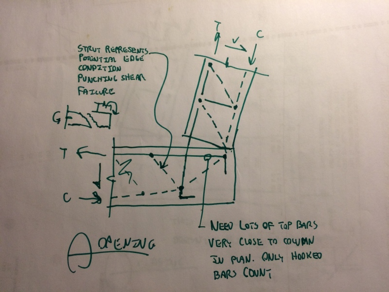
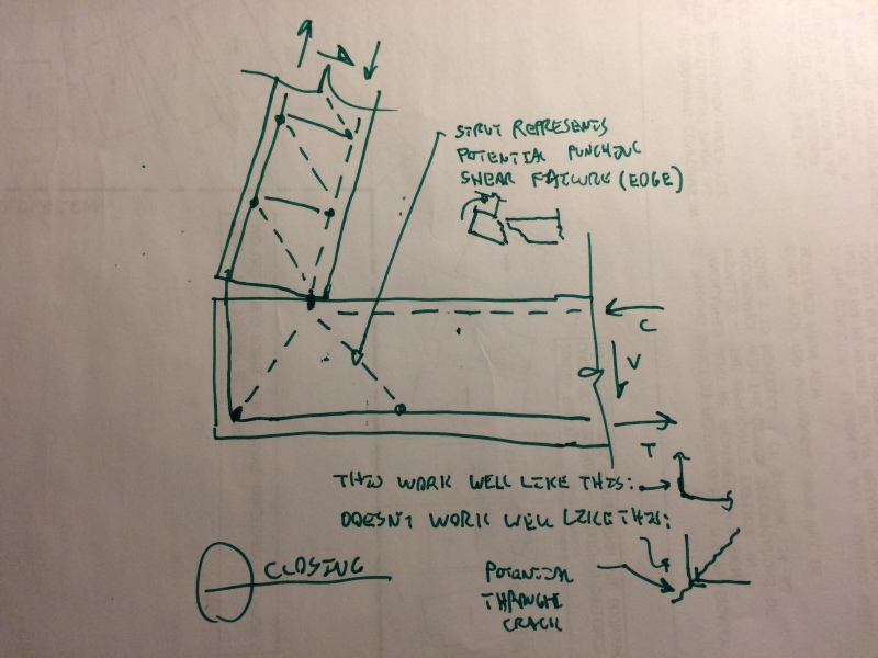
You can check the capacity using strut and tie procedures applied to the opening and closing models that I sketched above. Another way to look at it is to flip the model upside down in which case it becomes much like a roof level slab to column connection. The 270 kNm that I mentioned earlier was a ballpark number based on having to yield 8-20M column bars to over strength at a lever arm of 300 mm. I'd come up with a detailed estimate of your own before investing too much time on it.

I like to debate structural engineering theory -- a lot. If I challenge you on something, know that I'm doing so because I respect your opinion enough to either change it or adopt it.
 
This thread has some relevant information on the design of column connections that transfer moment: Link

I like to debate structural engineering theory -- a lot. If I challenge you on something, know that I'm doing so because I respect your opinion enough to either change it or adopt it.
 
You can check the capacity using strut and tie procedures applied to the opening and closing models that I sketched above. Another way to look at it is to flip the model upside down in which case it becomes much like a roof level slab to column connection. The 270 kNm that I mentioned earlier was a ballpark number based on having to yield 8-20M column bars to over strength at a lever arm of 300 mm. I'd come up with a detailed estimate of your own before investing too much time on it.

Ok. Thanks. Btw.. as the following combined footing layout shows (posted earlier) and highlighted in blue. There is a tie-beam of size 300mm width and 400mm depth about 1.5 meters above the combined footing connecting all the columns together.

..

Here is the picture of one.. we first put compacted sand to fill up 1.5 meters of the combined footing then add a tie-beam connecting each column for moment redistribution effect and to make the columns stiffer.

..

Now in seismic movement.. where does the base plastic hinges form? below in the combined footing or above the tie-beam?

Also about 0.5 meter above the tie-beam are the ground floor slabs of 4inches in thickness. With all these stiffening and in your experience.. where would the plastic hinge form? in the ground slab level? In the tie-beams 0.5 meter below it.. or in the combined footing 1.5 meters below the tie-beam?

Many thanks for the tips.
 
The tie beams will help a lot. You'd want the hinges to form at the top of the tie beams. You'd need to run some numbers to verify that though. That way, the end column to tie beam joint becomes critical rather than the column to footing joint. That's much better. Since your columns are bigger than your grade beams, developing the flexural over strength of your end columns may still be a challenge.

I like to debate structural engineering theory -- a lot. If I challenge you on something, know that I'm doing so because I respect your opinion enough to either change it or adopt it.
 
The tie beams will help a lot. You'd want the hinges to form at the top of the tie beams. You'd need to run some numbers to verify that though. That way, the end column to tie beam joint becomes critical rather than the column to footing joint. That's much better. Since your columns are bigger than your grade beams, developing the flexural over strength of your end columns may still be a challenge.

In the edge, the connections are a big question mark. How about in the center column as the following bar details show (they are spaced 6 inches apart and 20mm grade 60). Do connections at centers better or look adequate to supply the required strength (over-strength yield moment of the center columns)?

bottom bars:

..

with top bars:

..

If it looks adequate. I am hoping the center columns of each combined footing can restrain the edge columns via the tie beams and perhaps create better resistances. Whatever. Since even the ACI doesn't have clear guideless on this. I'd just avoid greater seismic mass and base shear and just use lightweight panel walls for the third floor instead of thick concrete wall.. and also light roofing.. Thanks for this realization.
 
The centre column connection looks fine. You seem to be missing a key point here however. Decreasing the seismic mass will not reduce flexural demand at these joints. Flexural demand is a function of supplied column strength.

I like to debate structural engineering theory -- a lot. If I challenge you on something, know that I'm doing so because I respect your opinion enough to either change it or adopt it.
 
The centre column connection looks fine. You seem to be missing a key point here however. Decreasing the seismic mass will not reduce flexural demand at these joints. Flexural demand is a function of supplied column strength.

But it will take greater seismic magnitude to reach these flexural yielding demands if there is help from restraining parts like tie beam or lowering base shear.. right? so instead of magnitude 7 making it fail.. it would take magnitude 8 or sorta...
 
We discussed that concept quite thoroughly in a previous thread I believe.

I like to debate structural engineering theory -- a lot. If I challenge you on something, know that I'm doing so because I respect your opinion enough to either change it or adopt it.
 
We discussed that concept quite thoroughly in a previous thread I believe.

Yes. On beam rotations or plastic hinges.

About the foundation-column base thing. I think the analogy is the beam flexural strength compared to columns flexural strength.. the column flexural strength must be stronger than beam to avoid weak column-strong beam.. this is written in most special moment frames references.. but there is practically none on computing column base flexural strength to the footing connections.. if you encounter specifically them.. please let me know in future by giving the references on this thread...

I think this is what you mean by avoiding fixed base connections.. because you need advanced connections in the footing. We spent about $10,000 extra on the combined footing. But you know in the Philippines.. most footing are spread footing and they are eccentric.. ignoring the kern thing. Combined footing is so rare here. Originally, the width of 1.5 meter is enough.. but the designer has to make it 2.5 meters width to avoid overturning etc.. after I told him to design combine footing after understanding eccentric footings are problematic with the entire column not able to take the moments of the eccentric foundation.

I think not a single structural engineer in the Philippines knows how to manually compute the footing-column base yielding capacity. Do you know of any online service say in New Zealand or Australia where they can check structural plans from abroad and do manual computations of each with a fee. Our structural engineers forget how to manually compute. And the contractors don't have any ideas about basic principles. So we need international help if we want to scrutinize something.

Thanks for much for all the help. Structural enginners in my place know less than 30% of your knowledge. All they do is use software and that's all.
 
I'd have to google firms in AU or NZ, same as you. In all honesty, concrete / seismic design and detailing seems a bit better in North America but not a lot better. And we're fast becoming software slaves as well. I wasn't being generous when I said that your footing detailing was better than most. It really is better than much of what is generated in my area.

Your building looks sturdy and well detailed in my estimation. I wouldn't be too hard on it or your design team.


I like to debate structural engineering theory -- a lot. If I challenge you on something, know that I'm doing so because I respect your opinion enough to either change it or adopt it.
 
Status
Not open for further replies.

Part and Inventory Search

Sponsor