Continue to Site

Eng-Tips is the largest engineering community on the Internet

Intelligent Work Forums for Engineering Professionals

  • Congratulations waross on being selected by the Eng-Tips community for having the most helpful posts in the forums last week. Way to Go!

Horizontal Trussing Threshold for Roof Diaphragm 3

Status
Not open for further replies.

mes7a

Structural
Aug 19, 2015
163
Hi,

How rigid must be the horizontal trussing in a roof before it can be considered a full fledge diaphragm? When the structure was constructed. They use 0.5x0.5 meter column from foundation all the way to third floor (it was designed for 4 storey).. but we decided now to build up to 3 storey only and plan to use thin metal roof to shed rain at gutter at side.

I know there must be a threshold in the horizontal trussing before the huge columns can become a diaphragm. For example. If you merely use a pole connecting the columns.. it can't be considered a diaphragm. Is it?

Also must the rafters be straight horizontal.. how about a bent gable rafter with apex at middle.. can a bent rafter create a diaphragm.. again what is the threshold of the rigidity? The pole is also rigid.. must it be certain strength compared to the huge columns?

Thank you.
 
Replies continue below

Recommended for you

That sounds very frustrating. That scribbled word was "potential". And column / footing bar continuity is exactly the issue. If you google "concrete opening joint efficiency" you'll see what it's all about.

Your comment above about poorly detailed eccentric footings is interesting to me. I worked through one of those designs with an Iranian friend who said the exact same thing about eccentric footing design practice in Iran. It's curious why something so fundamental is being routinely misunderstood/ignored.

I like to debate structural engineering theory -- a lot. If I challenge you on something, know that I'm doing so because I respect your opinion enough to either change it or adopt it.
 
That sounds very frustrating. That scribbled word was "potential". And column / footing bar continuity is exactly the issue. If you google "concrete opening joint efficiency" you'll see what it's all about.

Your comment above about poorly detailed eccentric footings is interesting to me. I worked through one of those designs with an Iranian friend who said the exact same thing about eccentric footing design practice in Iran. It's curious why something so fundamental is being routinely misunderstood/ignored.

The following is the original plan of the footing done by my designer. I posted it here 2 years ago to get feedback.. And many says it is silly, that the small column can't take the moments from the eccentric footing. So I got another designer with the idea of combined footing suggested here.

..

In the Philippines, most buildings have the footing above. The only reason for the combined footing thing is because of the feedback of people here. So thanks to them. Our designers mostly haven't done any combined footing. They just are good in eccentric spread footings.
 
By the way Kootk... won't the ground floor slab contribute to any diaphragm action on the columns making the plastic moments develope on the slabs instead? The slab is 4 inches thick with 10mm rebar spaced at 300mm o.c. and the concrete used is ready mix with tested compressive strength reaching 5000 psi..

Are you saying that when the column bases reach Mpr (yielding plastic hinges), it can bend against the slabs and just flex the slabs or can the slabs somehow restrain the columns? What usually occur here? Thanks.
 
Usually grade supported slabs are detailed with thin strip of compressible material around vertical elements like columns and walls. The purpose is to isolate these elements from one another for two reasons:

1) So that when the slab shrinks, the columns won't restrain it and cause unsightly slab cracking.
2) So that when the slab shrinks, it won't impose large lateral forces on the columns that could potentially fail them in shear.

Mostly it's #1. Anyhow, the end result is that your slab is generally not in direct contact with your columns and therefore is not a reliable form of restraint.

Even without the compressible strips, the slab on grade would still make for very questionable column restraint. If you worked out the compression force on the slab that would be delivered by the column in an over strength flexural yield scenario, it would be enormous. It would cause issues with:

1) The slab on grade crushing at the contact area.
2) The slab on grade buckling upwards.
3) The slab on grade sliding along the ground due to insufficient friction.

I like to debate structural engineering theory -- a lot. If I challenge you on something, know that I'm doing so because I respect your opinion enough to either change it or adopt it.
 
A special concrete moment frame has to develop plastic hinges at the column bases. As such, the moment demand at the base of the columns is equal to the over strength flexural capacity of the columns at minimum.

But most special moment frame has pinned column bases (such as from spread footing).. you yourself said pinned bases are more normal because it's so expensive to make fixed bases (we spent over $10,000 *additional* for it and still not perfect).. the only reason for our fixed bases is because it is a combined footing..

For pinned bases.. can you still say special moment frame has to develope plastic hinges at the column bases? But if you will see the column moment diagram.. there is no (or not much) moment at the base because it's pinned so how can the base develope plastic hinges?

And why does special moment frame has to develope plastic hinges when the advantage of fixed bases are mostly in the ground floor (like tall ground storey).. and it won't affect the beam shear in the upper story nor the drift, as we discussed previously?

Anyway. If my foundation doesn't have the moment capacity to resist the column flexular over strength.. I could have use only a few bars (just like you use dowels) at beginning connecting to the bottom of the foundation to make it pinned, isn't it (obeying ACI 0.005 dowel steel ratio in the footing). But since the foundation already casted 2 years ago. Then this is is for knowledge and not actually trying to cut the bars to make it pinned.
 
Kootk,

The tie beams will help a lot. You'd want the hinges to form at the top of the tie beams. You'd need to run some numbers to verify that though. That way, the end column to tie beam joint becomes critical rather than the column to footing joint. That's much better. Since your columns are bigger than your grade beams, developing the flexural over strength of your end columns may still be a challenge.

The tie beams may not work. There is only 3 bars at the top of the beam (crossing joint) and 2 bars below. Remember the tie beam is 1.5 meters up the combined footing. Between it are soils. In my country, we use tie beam to restrain small eccentric footing. So the designer just left out the original tie beam to restrain small eccentric footing. He doesn't design it to make the plastic hinge develop above it. Anyway. I wonder how beam would behave if they are restrained by soil.. you can't call it a grade beam entirely because it is not rested on footing elevation. But then soil is soft material, so the entire column may just move against the tie beam and plastic hinges form back to the combined footing joint.

So I'll have to determine if the column joint right in the foundation has the overstrength capacity to handle the column moments. Before I'll search for any expert (if there is even one) in my country who can compute for it (or do you know of people right there in your place where they can do detailed calculations at a fee for peer review?). I'd like to understand some basic concept. I found the details about column at edge of slab at the book Reinforced Concrete: Mechanics and Design by James K. Wight. See:

aYPcyu.jpg


5gljB5.jpg


There are many ACI methods to compute for it. However. It's mostly about slabs directly connected to columns above. Can you treat the foundation with edge column as slabs on columns and is the analysis the same? I'd want to explore the ACI methods. I don't want to try the harder strut and tie method you mentioned earlier because I don't understand them. I'm more familiar with the more familiar beam method or others that don't use strut and tie.

I need expert help. Do you know anyone in your place who can help? In my country. There is not enough sophistication to handle this analysis, although I will seek for one.. but need to know some basic so I can even ask the proper questions to him.

I want to determine if my edge column overstrength moment can be taken up by the foundation connection and detailing. If not. Then would go for retrofit of the existing tie-beam, maybe even replacing all the soil with concrete to change the plastic hinge above or reinforce the tie-beam with thick metal plates to transfer the plastic hinge above. Of course I'll find an expert in my country (if there is even one) for this. So I just need some initial thoughts of how to discuss with him.

Also if you will see the first picture above. The slabs are thin. But my foundation is very thick compared to the thin slabs presented above.. my foundation is 0.6 meters deep and 2.5 meters wide. Using the Vc equation of 2phi* sqrt (fc')* bw x d .. my Vc shear capacity is about 1200 kN. Now with 270 kN.m overstrength moment of the column.. can't you just use Shear x distance to get *rough* estimate of the moment capacity?

Don't worry. I'll let experts handle this. But just want initial guide of how to even present this to them. Thank you.
 
You've taken some of my previous comments regarding pinned based columns out of context I'm afraid. I recommend pinned based columns for steel columns that are not a part of a moment frame. For special moment frames, I always utilize base fixity. This is because, in practice, it is very difficult to create a truly pinned column base and it isn't something that you would want to be wrong about in the case of a special moment frame where the stakes are high. And creating a truly pinned column base in concrete construction is particularly difficult.

mes7a said:
And why does special moment frame has to develope plastic hinges

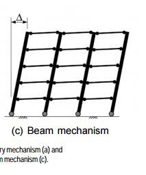
Because a special moment frame must form a complete mechanism at some point in its load history. Otherwise, it will continue to attract additional seismic load until some other, unintended member, reaches the limit of it's load carrying capacity and fails. This is a crucial part of the capacity design concept. Notice that, in the graphic below, yielding every beam at each end still would not produce a complete mechanism unless hinges also formed at the column bases. FYI: a complete mechanism is one which would render the frame incapable of resisting further lateral load. In a static load situation, it would represent collapse.

I think that the best bet for your building is to simply abandon the special moment frame concept. Analyse the structure as an ordinary or intermediate moment frame system where the demand on the joints is much less. I believe that this would work as your building is small and has several moment frames in each direction. Frankly, I very much doubt that it was necessary to eliminate the upper floor of the building. Do you have any concrete elevator or stair shafts in the building?

CAPTURE_u6eesp.jpg


I like to debate structural engineering theory -- a lot. If I challenge you on something, know that I'm doing so because I respect your opinion enough to either change it or adopt it.
 
mes7a said:
or do you know of people right there in your place where they can do detailed calculations at a fee for peer review?

The trick with this would be that, for most corporate entities, the risk/reward ratio would scare people off. I know that, if I brought this to my company, they'd be terrified of the liability and insurance issues and would charge you a ridiculous fee to compensate for that. That, or they'd just reject it outright. You'd probably need to find someone who possessed their own small firm and could do as they pleased. I can do one thing for you however. If you can talk your local engineer into letting you post his calculations here, I'll review them and provide comment. No charge of course.

mes7a said:
Can you treat the foundation with edge column as slabs on columns and is the analysis the same?

Yes, quite right. I think that you might be gradually turning into your area's best structural engineer. The main reason for which I would prefer strut and tie is that such an analysis tends to do a better job of highlighting the need for developed top reinforcing close to the column. What it would amount to, more or less, is all of the moment at the connection needing to be dealt with by rebar that is:

a) crossing the potential yield line in the sketch that you clipped above and'
b) developed past that potential yield line.

mes7a said:
The slabs are thin. But my foundation is very thick compared to the thin slabs presented above.. my foundation is 0.6 meters deep and 2.5 meters wide.

It's very astute of you to make this observation. The ACI slab method is intended for thin things and strut and tie is usually more appropriate for thick things. That being said, it's more about the ratio of column depth to slab depth than the absolute thicknesses. At 650/400, I'd still consider the slab method applicable. The Wight textbook is one of my favorites. I know for a fact that there's an excellent treatment of two way punching shear in there someplace.

mes7a said:
Using the Vc equation of 2phi* sqrt (fc')* bw x d .. my Vc shear capacity is about 1200 kN. Now with 270 kN.m overstrength moment of the column.. can't you just use Shear x distance to get *rough* estimate of the moment capacity?

no. You're checking one way shear here when the primary issue will be two way shear. If you google those terms, you'll quickly get a sense for the difference.


I like to debate structural engineering theory -- a lot. If I challenge you on something, know that I'm doing so because I respect your opinion enough to either change it or adopt it.
 
I actually checked punching shear on your column / footing connection back when we first started looking at it and it appeared that you had plenty of capacity there.

Punching shear on the column/footing connection is not the same as flexural overstrength of the column footing connecting at yielding.. isn't it? Are you just referring to the axial load in the punching shear?

My designer with team of 10 all use software. They literally forget how to compute (because it would be taxing to manually compute 30 storeys). Last week I was asking for beam computations. They told me they can just output the results in Etabs. They design many 30-storeys in the country. See their website at:


They use SAFE software in the design of the foundation. SAFE should adequately handle punching shear.. but I don't know if it can check for design of column/footing flexural overstrength. I'll get the software myself to familiar with it so I can ask the designer next week how they designed it to check on the overstrength capacity (the person who input the program has already left their company so it would be others among them who would check it so I need to familiarize myself what to ask).

By the way. When the axial load is above the balance point of the interaction diagram, there is less moment capacity.. in other words.. can the column-footing really develop the overstrength at yielding without the compression side of the column crushing first?
 
Thanks for sharing the link to your consultant's website. I agree, they have an impressive portfolio of completed work.

mes7a said:
Punching shear on the column/footing connection is not the same as flexural overstrength of the column footing connecting at yielding.. isn't it? Are you just referring to the axial load in the punching shear?

The punching shear check accounts for both axial load and moment effects. As long as the applied moment in the check is that corresponding to the flexural over strength of the column, then flexural over-strength is accounted for. In my checks, I included the moment but ignored the axial. I did that because I don't know the axial and I suspected that the moment would dominate.

mes7a said:
They use SAFE software in the design of the foundation. SAFE should adequately handle punching shear

As I mentioned above, it should just be a matter of applying the right moment to the safe model. Beyond that, there is nothing unusual about the check.

mes7a said:
By the way. When the axial load is above the balance point of the interaction diagram, there is less moment capacity.. in other words.. can the column-footing really develop the overstrength at yielding without the compression side of the column crushing first?

This is a valid concern. It is for just this reason that the axial component of column stresses is kept low for special moment frames in ACI. They are limited to a small ratio of f'c I believe.

I like to debate structural engineering theory -- a lot. If I challenge you on something, know that I'm doing so because I respect your opinion enough to either change it or adopt it.
 
The punching shear check accounts for both axial load and moment effects. As long as the applied moment in the check is that corresponding to the flexural over strength of the column, then flexural over-strength is accounted for. In my checks, I included the moment but ignored the axial. I did that because I don't know the axial and I suspected that the moment would dominate.

you mentioned that column at edge of footing needs special detailing which involves top bars and if there is enough in in yield lines which needs close spacing. this is different from the punching shear you talked about above isnt it? because punching shear one way and two way shear can be calculated for footing with just bottom bar. so in the above description are you simply talking about the generic punching shear or did your calculations also include the yield lines of the top reinforcing bars of the flexural overstrength? if so', what computations methods did you use? many tnx. kootk.. you must be nominated as an officer of the Canadian Structural Society :)
 
mes7a said:
so in the above description are you simply talking about the generic punching shear or did your calculations also include the yield lines of the top reinforcing bars of the flexural overstrength?

It was just the generic punching shear design and not the yield lines. There is an odd feature built into how punching shear is checked. Punching shear checks are predicated upon concurrent, correct flexural design. This is not always apparent to designers, however, as the presentation in codes rarely highlights this. Basically, if your joint flexural capacity is junk, so is your joint shear capacity. This article does a good job of explaining this: Link

mes7a said:
if so', what computations methods did you use?

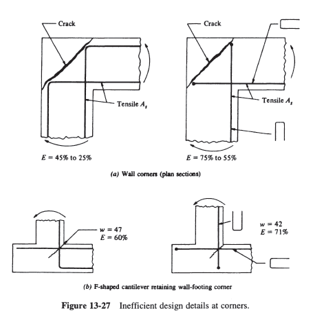
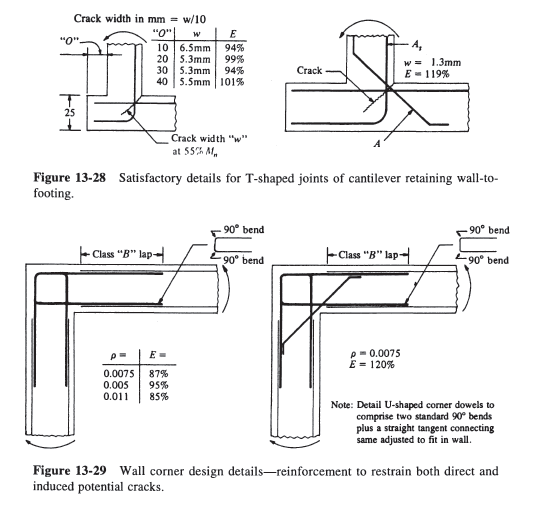
As I mentioned above, I would use the strut and tie approach for a high stakes situation like the connection between a special moment frame and its foundations. Using the slab punching shear concept is valid, I believe, and no doubt simpler to execute. I just don't have the same level of comfort regarding the results that I would with a strut and tie design. The sketches below show efficiency ratings for wall corner joints detailed in different ways. While none is exactly your scenario, I think that the sketches will help you to understand my concern for the careful detailing of the joint. If anything, the detailing would be more demanding in a column/slab joint than it would be in a wall/wall joint as the forces are more concentrated.

Capture01_oc0enl.png

Capture02_p3mdtw.png


I like to debate structural engineering theory -- a lot. If I challenge you on something, know that I'm doing so because I respect your opinion enough to either change it or adopt it.
 
mes7a said:
kootk.. you must be nominated as an officer of the Canadian Structural Society :)

I wish. Such appointments usually go to those who are more skilled at self promotion than I. Thanks for the kind words though.

I like to debate structural engineering theory -- a lot. If I challenge you on something, know that I'm doing so because I respect your opinion enough to either change it or adopt it.
 
It was just the generic punching shear design and not the yield lines. There is an odd feature built into how punching shear is checked. Punching shear checks are predicated upon concurrent, correct flexural design. This is not always apparent to designers, however, as the presentation in codes rarely highlights this. Basically, if your joint flexural capacity is junk, so is your joint shear capacity. This article does a good job of explaining this: Link

Have you used the software SAFE? Does it include the yield lines in the determination of the punching shear design? If manual would show it is inadequate.. then retrofit solutions would be logical.

In many designs of eccentric spread footing in my country. They put tie beam to prevent settlement and to distribute the moments. It is not a true grade beam to create base fixity.. which you mentioned before needs to be deeper and to be at the elevation of the footing surface. So the above tie beams are just standard we use.. not designed to transfer the plastic hinges above. But imagine the column-tie beam joints are being pinned from lateral movement from fixed.. in normal column-beam joints, the deflections occur because the beam is free to deflect.. but in the picture above.. the compacted soil restrain the beam from deflecting below.. would this increase the flexural capacity of the tie beam? Again the tie beam has only 3 pcs of 20mm rebar at top of its joint (for positive moment) and 2 pcs below. This won't make it great flexurally.

By the way. About eccentric spread footing. It doesn't have top bars. If the joint doesn't have the overstrength flexural capacity.. would it have the same punching shear capacity deficiently or would it compensate by becoming pinned when the entire foundation just rotate against the soil?

Going back to retrofit. Straightening the tie beam joints by enclosing it with metal plates or putting pedestral or even putting mini columns in between the tie beams to support the tie beams may make the connections more fixed and transfer the plastic hinge above.. isn't it.. what is your experience in this and what could be possible retrofit you think can work in the column-tie beams joints and below to make the plastic hinge develop above? Many thanks.
 
By the way Kootk.. is the potential yield lines where the cracks would be?

y9v8aa.jpg


Or is it in the same area as the 2 way punching shear?

d43ipc.jpg


Do you have picture of any such cracks where it differs from the punching shear cracks?

Also in sides.. the columns are bowing inwards because of eccentric loading so the CLOSING case is more the average situation as follows right? so the very closed spacing of longitudinal bars near the yield lines is not the for the "closing" loading case or scenerio.

FmhFgT.jpg


I think the opening would only occur during reverse cyclic loading.. but if the columns are bowing inwards in the sides of the structure.. won't it be possible there is no reversed cyclic loading and the "Opening" case won't occur?

I need to present this to my designer. Unfortunately he doesnt understand the meaning of stress-strain diagrams last time. Because last time he told me to inject epoxy to a 2 inch void in the columns.. but hokie adviced against it saying the epoxy modulus of elasticity differs so much to concrete that it won't be compatible in the strains and compressions. This is the reason I started to focus understanding manual computations of the interaction diagram and the structure to understand the loadings.

Many many thanks. I want to send you amazon gift coupon if possible for giving so much useful tips :)
 
It was just the generic punching shear design and not the yield lines. There is an odd feature built into how punching shear is checked. Punching shear checks are predicated upon concurrent, correct flexural design. This is not always apparent to designers, however, as the presentation in codes rarely highlights this. Basically, if your joint flexural capacity is junk, so is your joint shear capacity. This article does a good job of explaining this: Link

I have read your link over and over again as well as more references for hours in preparation to presentation to the designers. Last time they failed to understand what I was explaining about stress-strain diagram and pure epoxy (not epoxy grout) filling up of voids. In our country. We fill up even 2 meters of voids in high rise building column bases with epoxy (there is no other solution).

Anyway. In reading all the references about yielding lines at slab-column that doesn't use beams. I realize they are all about your CLOSING case.. because the slabs don't anti-gravitate up the air... it goes down or closes with respect to the column. There in the foundation analogy, the bottom bars are the concerns. The yield lines in the books concern the bottom bars. My bottom bars near edge were extensive.

The references on slab-column without beams doesn't handle your OPENING case. Right? There if the top bars of the foundation near the edge is insufficient.. there is possibility of punching shear failure at column flexural overstrengh. However if the punching shear capacity is a lot.. it may make it. I don't think any insufficient top bars can crack the top in tension (like in bottom of beams in tension). Would it? Using the strut and tie analogy. Any insufficient tie in the Opening case would mereLY cause punching shear.. but if the punching shear capacity is a lot.. it may calc out.. what you think? I just need to master the concepts so I know how to debate with the designers.. so many many thanks Kootk.

 
After reading many books more. I finally got your core ideas. Kootk.. I finally am confident how to present the ideas to my designers. The moments of the column has to be carried to the footing.. and moment transfer by shear stress is not enough to do it.. but has to be carried by flexure. I'll emphasize this to them tomorrow. Because they would reason 2 way punching shear can take care of both moments and axial load. I'll say this is the not the issue I'm concerned.. but the yield of the joint itself just like column flexural must be stronger than beam's flexural. Last time I tried to share them ideas of stress-strain incompatibility of concrete and pure epoxy. They won't believe it. So don't blame me if I get a bit paranoid on all this. So many many thanks to you Kootk. I think you must get a reward for great service to the public. You would make a very good educator perhaps as professor :)

 
Ok, we'll leave it at that then mes7a. I hope that you have a fruitful discussion with your engineers tomorrow.

I like to debate structural engineering theory -- a lot. If I challenge you on something, know that I'm doing so because I respect your opinion enough to either change it or adopt it.
 
Ok, we'll leave it at that then mes7a. I hope that you have a fruitful discussion with your engineers tomorrow.

Oh, last thing I wanna know before getting into formal discussions with them.

I know base shear is computed from the sum of all forces above.. however, in high rise, the flexibility of the building would produce less forces that could even make the base shear of 30-storey vs 4 storey not far. For example.

4 story building - 20m x 30 m residential in Zone -3 on a hard rock. R = 3 and I = 1.
Approx time period = 0.4 sec
Approx loading = 12 kn/m2
Total Base shear (using IS1893) = 6.7% of seismic weight = 20x30x4x12x6.7/100 = 1930 kn.

30 story building - 20m x 30 m residential in Zone -3 on a hard rock. R = 3 and I = 1.
Approx time period = 3.0 sec
Approx loading = 15 kn/m2 (as columns and walls will be much thicker)
Total Base shear (using IS1893) = 0.9% of seismic weight = 20x30x30x15x0.9/100 = 2430 kn.

As you can see, the 4 story building has relatively very high base shear (about 80% of 30-storey building).

Now I'd like to know the relationship of base moments to base shear. From base shear alone.. can you get estimated values of the base moments.. is there a direct formula that relates the two? Does building flexibility also affect the base moments.. or is the base moments related to all the beam moments above. You know yield base moments would occur from increasing base moments up to forming plastic hinges.

I'm asking all these because I wonder how big is the column-footing joint flexural demands in high-rise buildings compare to 4 storey (or 3 storey). Remember my designers handle high-rise.. so if they fail in my footing design.. they may miss it too in high-rise. And I'll get to the bottom of it (pun intended).

This is the last question for this long thread. Thanks a million Kootk!
 
Status
Not open for further replies.

Part and Inventory Search

Sponsor