Continue to Site

Eng-Tips is the largest engineering community on the Internet

Intelligent Work Forums for Engineering Professionals

  • Congratulations waross on being selected by the Eng-Tips community for having the most helpful posts in the forums last week. Way to Go!

Horizontal Trussing Threshold for Roof Diaphragm 3

Status
Not open for further replies.

mes7a

Structural
Aug 19, 2015
163
Hi,

How rigid must be the horizontal trussing in a roof before it can be considered a full fledge diaphragm? When the structure was constructed. They use 0.5x0.5 meter column from foundation all the way to third floor (it was designed for 4 storey).. but we decided now to build up to 3 storey only and plan to use thin metal roof to shed rain at gutter at side.

I know there must be a threshold in the horizontal trussing before the huge columns can become a diaphragm. For example. If you merely use a pole connecting the columns.. it can't be considered a diaphragm. Is it?

Also must the rafters be straight horizontal.. how about a bent gable rafter with apex at middle.. can a bent rafter create a diaphragm.. again what is the threshold of the rigidity? The pole is also rigid.. must it be certain strength compared to the huge columns?

Thank you.
 
Replies continue below

Recommended for you

mes7a said:
This is the last question for this long thread.

Keep asking until you've gotten what you need. Don't worry about me; I'll withdraw if I get exhausted. I don't even consider a thread to be the real deal unless the replies get to triple digits!

mes7a said:
Now I'd like to know the relationship of base moments to base shear.

First, we need some definitions:

M_e = seismic moments calculated from code procedures as you have done above. These should scale up and down in direct proportion to the base shears. Flexibility results in lower moments.

M_o/s = over strength moment of your columns that depends only on the column section propertiess (column size, rebar, f'c, etc).

In a new design, things unfold like this:

1) Find M_e
2) Design column for M_e while minimizing ratio M_o/s / M_e
3) Design footing for M_o/s.

In the above case, M_o/s will obviously rise and fall with base shear.

When analyzing an existing situation, M_o/s is whatever it is based on the column section properties and neither M_e nor the base shear will enter into the equation. This is your case I believe.


I like to debate structural engineering theory -- a lot. If I challenge you on something, know that I'm doing so because I respect your opinion enough to either change it or adopt it.
 
Keep asking until you've gotten what you need. Don't worry about me; I'll withdraw if I get exhausted. I don't even consider a thread to be the real deal unless the replies get to triple digits!

You deserved a vacation in the Bahamas for this :)
But I'd just want to know some basics and leave it to the experts as this is not my job. My job is just to live in the building.

First, we need some definitions:

M_e = seismic moments calculated from code procedures as you have done above. These should scale up and down in direct proportion to the base shears. Flexibility results in lower moments.

M_o/s = over strength moment of your columns that depends only on the column section propertiess (column size, rebar, f'c, etc).

In a new design, things unfold like this:

1) Find M_e
2) Design column for M_e while minimizing ratio M_o/s / M_e
3) Design footing for M_o/s.

In the above case, M_o/s will obviously rise and fall with base shear.

When analyzing an existing situation, M_o/s is whatever it is based on the column section properties and neither M_e nor the base shear will enter into the equation. This is your case I believe.

But if a structure lateral resisting sytem is composed of shear wall or braced frames.. the column bases won't reach Mpr (hence there would be no yielding).. isn't it? This is the reason why if you can alter the building main seismic resisting system, you can avoid column base plastic hinges (or would this still occur even with braced frames?)

Earlier you asked me this:

I think that the best bet for your building is to simply abandon the special moment frame concept. Analyse the structure as an ordinary or intermediate moment frame system where the demand on the joints is much less. I believe that this would work as your building is small and has several moment frames in each direction.

But a special moment frame includes vertical lateral system that are all special moment frame and even included fixed foundation.. so why make R=5 by analyzing it as ordinary or intermediate moment frame?

Frankly, I very much doubt that it was necessary to eliminate the upper floor of the building. Do you have any concrete elevator or stair shafts in the building?

OjA03L.jpg


There is no elevator shaft.. only stair shafts and it is in the lower right side of the building. It may not serve as major lateral resisting system, would it.. it may even introduce torsion. What concerns me is the transverse side main lateral resisting system of the building is purely special moment frame.. not even have walls to make it stiff or shear wall nor braced frame. For the 30-story high rise.. their lateral resisting system is stiff elevator shafts. So my building column base seemed to have much more demand than high-rise.

Again, for high rise buildings with elevator shaft as main lateral resisting system and other rigid shear wall or bracing, would the moments in the column bases in the foundation be much that can make it into yielding moments?
 
mes7a said:
But if a structure lateral resisting sytem is composed of shear wall or braced frames.. the column bases won't reach Mpr (hence there would be no yielding).. isn't it? This is the reason why if you can alter the building main seismic resisting system, you can avoid column base plastic hinges (or would this still occur even with braced frames?)

This is mostly right. If you have shear walls, your column bases are unlikely to reach Mpr. If you have braced frames, the bases that are part of the braced frames will have to reach Mpr. Again, there's no other way for the braced frames to form complete hinges unless the bases yield. But yeah, this is a valid strategy for protecting your column bases from over-strength bending forces.

mes7a said:
But a special moment frame includes vertical lateral system that are all special moment frame and even included fixed foundation.. so why make R=5 by analyzing it as ordinary or intermediate moment frame?

What's killing you with the special moment frames is that you're not designing for the earthquake forces at all (M_e). Instead, because you have special moment frames, you're designing for the moment capacity of your columns. If you go OMF, M_e might go up but you will no longer need to consider M_o/s.

mes7a said:
only stair shafts and it is in the lower right side of the building. It may not serve as major lateral resisting system, would it.. it may even introduce torsion

With the shaft walls considered, I anticipate that the building will function as shown below where the only active moment frames are those shown in purple. The other moment frames will be prevented from participating by the presence of the relatively stiff shaft walls that prevent those frames from deforming freely. All tolled, this is probably great news for your building.

mes7a said:
gain, for high rise buildings with elevator shaft as main lateral resisting system and other rigid shear wall or bracing, would the moments in the column bases in the foundation be much that can make it into yielding moments?

No. The elevator shaft walls would keep interstory drifts so low that the columns would not develop large enough moments to cause yielding. At least, that's the idea.


I like to debate structural engineering theory -- a lot. If I challenge you on something, know that I'm doing so because I respect your opinion enough to either change it or adopt it.
 
What's killing you with the special moment frames is that you're not designing for the earthquake forces at all (M_e). Instead, because you have special moment frames, you're designing for the moment capacity of your columns. If you go OMF, M_e might go up but you will no longer need to consider M_o/s.

What? You are saying you can analyze special moment frames as ordinary moment frames? This is the most confusing sentences you have written in all :)

Are you saying that because I built only 3 storey out of the designed 4 storey and the columns are bigger than normal.. it can be considered ordinary moment frames??

With the shaft walls considered, I anticipate that the building will function as shown below where the only active moment frames are those shown in purple. The other moment frames will be prevented from participating by the presence of the relatively stiff shaft walls that prevent those frames from deforming freely. All tolled, this is probably great news for your building.

No the shaft walls are very soft.. it is just ordinary stairs.. only the steps are rigid.. we don't build rigid stair shafts.. the walls are just thin 4" hollow blocks mildy reinforced that you can put a hole with just using hammer.. so it won't have active particular in seismic activity in the lateral sides.. it is still the columns that resist them.
 
mes7a said:
You are saying you can analyze special moment frames as ordinary moment frames?

That's exactly what I'm saying. The loads go up but the requirement for over-strength design goes away.

mes7a said:
Are you saying that because I built only 3 storey out of the designed 4 storey and the columns are bigger than normal.. it can be considered ordinary moment frames??

I'm saying that it's an alternative worth investigating. I would wager that it would work out even with the 4th floor.

mes7a said:
No the shaft walls are very soft.. it is just ordinary stairs.. only the steps are rigid.. we don't build rigid stair shafts.. the walls are just thin 4" hollow blocks mildy reinforced that you can put a hole with just using hammer.. so it won't have active particular in seismic activity in the lateral sides.. it is still the columns that resist them.

Agreed.

mes7a said:
Why.. in your country.. do you build solid shear wall stair shalf.. why would you do that??

1) So we don't need moment frames.
2) The cost of a concrete wall versus an infill wall constructed to be fire resistant seems to be about the same.


I like to debate structural engineering theory -- a lot. If I challenge you on something, know that I'm doing so because I respect your opinion enough to either change it or adopt it.
 
That's exactly what I'm saying. The loads go up but the requirement for over-strength design goes away.

Hmm.. but people built special moment frames so the R would be 8.. it should behave as special moment frames.. why would it becomes ordinary moment frames in reality??

Hmm.. did you mention all this because my columns are bigger than normal (even for 4 storeys)? Because if they are small making R exactly 8 and flexible.. it won't behave as ordinary moment frames at all.
 
OP said:
Hmm.. but people built special moment frames so the R would be 8.. it should behave as special moment frames.. why would it becomes ordinary moment frames in reality??

We use high R values so that we can use low design forces. Conversely, if a structure can handle higher design forces, we can use design and detailing procedures associated with lower ductility demands (low R). The only difference between an OMF and an SMF is that you can push an SMF a lot farther before it falls apart. About four times farther. Of course, if you never need to push quite so far, all the better.

OP said:
Hmm.. did you mention all this because my columns are bigger than normal (even for 4 storeys)? Because if they are small making R exactly 8 and flexible.. it won't behave as ordinary moment frames at all.

I mentioned it because:

1) your columns are big.
2) your building is short.
3) you've got moment frames all over the place.
4) I know that you've lopped off a whole story.

All of these things point to reserve pre-plastic hinging capacity. Reserve strength that you can mobilize before anything is required to yield.

I like to debate structural engineering theory -- a lot. If I challenge you on something, know that I'm doing so because I respect your opinion enough to either change it or adopt it.
 
I mentioned it because:

1) your columns are big.
2) your building is short.
3) you've got moment frames all over the place.
4) I know that you've lopped off a whole story.

All of these things point to reserve pre-plastic hinging capacity. Reserve strength that you can mobilize before anything is required to yield.

The reason I lopped off a while story is because of the epoxy ejected in a 4 inch thick honeycombs in one of the columns near footing. See:

zgJwbI.jpg


If you get it to a compressive strength test. It's about 8000 PSI. The designers said it's even stronger than concrete and most designers used it here whenever there are honeycombs in the columns or beams (honeycombs are common because of extremely bad construction practice in the country). But after numerous computations with experts in eng-tips. We determined there was a loss of about 1000kN (with 2000kN left with the building 1000kN actual live, dead and sd load) capacity in the epoxy section (due to modulus of elasticity and strain incompatibility between epoxy and concrete). But the designers couldn't understand what I'm saying after showing him the computations and reminding him about stress-strain diagrams. So I gave up and just decided to go for 3 storey as safety margin.

Anyway. I talked with the designer a while ago about the flexural overstrength in the column-footing joint capacity you mentioned at length here. Again, they said punching shear is sufficient. I emphasized it's the joint flexural moment transfer that may not occur and can yield. They said the footing has been designed for punching shear. They can't seem to understand the concept of joint moment transfer of column base to footing by flexure or tie in the strut and tie model (which they don't use). But then maybe they don't really design for special moment frames which you said depends on column moment capacity. Even before designing the beams, they already had decided to make the column 0.5x0.5 (and 0.5x0.4) meter. If you will use pure special moment computations, the size of the joint and column depends on the beams probable moment strength. But it seems they don't follow it. What happens.. based on your earlier explanation is they designed it as ordinary moment frame with big columns and lower R that can resist earthquake moments and base shear. This is the only logical thing possible based on what they described and what you described. Whatever, even with ordinary moment frame anywhere, if you have magnitude 9 earthquakes. The column-footing joint would go into overstrength flexure (forming plastic hinges) isn't it? Or would there be shear failure first before plastic hinges forming in column base in ordinary moment frames at maximum earthquake magnitude (say 9)?

Anyway. I just plan to building up to 3 storey with light roof (and possibly light wall). But now I'm worried the resonance of the soil/rock underneath can match the period of the building. When there is resonance.. how many times would the seismic movement be compared to non-resonance case? Because if the 3-storey with light roofing would be in resonance with the soil. It would be worse than having heavier roofing. And should there be resonance.. I'd use heavier roofing like steel deck and heavier wall to desynchronize the resonance. Any experience with computing for soil and building resonance effect? Don't blame me for being paranoid. I don't know where to find local designers who know about the epoxy strain incompatibility and the column base-footing joint flexure capacity that international experts in eng-tips know about. So I'm very cautious now of everything. Again Thanks a zillion.
 
To continue what I said in middle paragraph above.

We use high R values so that we can use low design forces. Conversely, if a structure can handle higher design forces, we can use design and detailing procedures associated with lower ductility demands (low R). The only difference between an OMF and an SMF is that you can push an SMF a lot farther before it falls apart. About four times farther. Of course, if you never need to push quite so far, all the better.

I've been thinking of this for hours. And this is the confusing part. If the structure can handle higher design forces.. yet you use detailing procedures associated with lower ductility demands (low R), then would there be ductility or not.. We design special moment frames to resist higher seismic load because the yield displacement can absorb a lot of energy.. hence the "ductility" part.. yet you said above about using detailing procedures with lower ductility demands in structure that can handle design forces.. which seems to be in contradiction because when you use low ductility detailing, shear failure can occur from beam plastic hinges. I'm asking this because my beams were heavily retrofitted with carbon fiber and so many hoops in the hinging ends. They are designing for higher ductility. Would they be mobilized when the elastic limit of the bigger columns have been used up? If yes.. then the right words to say is "Conversely, if a structure can handle higher design forces, we can use design and detailing procedures associated with HIGHER ductility demands (High R) too." Then you will end up with an Adaptive R and Hybrid OMF/SMF where they can be push 4 times farther also. Is it not?

I mentioned it because:

1) your columns are big.
2) your building is short.
3) you've got moment frames all over the place.
4) I know that you've lopped off a whole story.

All of these things point to reserve pre-plastic hinging capacity. Reserve strength that you can mobilize before anything is required to yield.
 

By the way. We are less than 10 kilometers away from a major fault line that can create magnitude 7 earthquake in the capital of our country. Therefore I think it's not a good idea to consider it going back to Ordinary Moment Frame. I think the better description would be special moment frames all along. So what if my columns are bigger. It's just like the case of high-rise where the lower storey has bigger column.. it can only attract the moments away from beams. But it's all special moment frames all the way. Do you agree with this? Let's call it Adaptive R then with columns that can work initially from lower R but then go to higher R as seismic activity increases in magnitude enough to make the columns drift into ductile mode (and consequent plastic rotations of the beams). ??
 
If a building had no ductility, then we would design it for an R value of 1. There is inherent damping in the system, which is why we use R values to reduce the seismic load. In high R value systems, we use special detailing to allow plastic hinges to form in certain locations, which further dissipates energy and leads to a higher R value. In low R value systems, like ordinary moment frames, we do not pay special attention to detailing because it is often times very expensive and the loads are not large enough to require the special detailing. In fact, steel special or intermediate moment frames have compactness criteria that limits the size of beams and columns that can be used. So in a low seismic region, it is not economical to use a higher R value system. It's important to note that most design codes will not allow the use of low R value systems in regions with high seismic potential. Also, the R value doesn't change as seismic activity increases. You design and detail for one force, usually what is expected from a 500 year mean recurrence period for seismic events.

All that being said, I think you have a good basic understanding of what the goal is in seismic design. However, I think you should review some basic concepts within structural dynamics and how seismic loads travel through the building to get a better understanding of designing for high seismic regions. These are basic concepts of structural engineering for lateral design and are critical to understand in high seismic regions. Most of your questions can only be answered by modeling and applying loads to see how the frames behave. It's not very intuitive (for most) to predict what happens in a frame as you started changing detailing and frame proportions.
 
I've been reading Iranian literature on it to getting a handle of what Kootk is saying.


It concludes: Selecting a higher ductility level increases transverse reinforcements and then it will increase the weight of these bars. However, on the other hand, for ductile frames we can consider small seismic loads, which consequently decrease the longitudinal reinforcements.

Do ductile frames (special moment frames) have lower longitudinal reinforcements than ordinary frames?

Kootk golden words were "We use high R values so that we can use low design forces. Conversely, if a structure can handle higher design forces, we can use design and detailing procedures associated with lower ductility demands (low R). The only difference between an OMF and an SMF is that you can push an SMF a lot farther before it falls apart. About four times farther. Of course, if you never need to push quite so far, all the better."

For ordinary moment frames that deal directly with the seismic forces (M_e). Can't it be make ductile too? Or does increase longitudinal bars used in ordinary moment frames means they can't be made ductile?? Is this what Kootk mean?

I'm afraid my building which has been designed to resist maximum earthquakes with less than 10km from a fault line has been turned into ordinary moment frame instead of special moment frames unfortunately. Is this it? Maybe making the columns bigger create this unfortunately scenario of weakening seismic resistance because it has to face large seismic forces (bec not flexible.. making R less)
 
The size and number of longitudinal bars are a function of the force going into them. It all depends on frame configuration and the forces (gravity and lateral) at each frame.

If you do not meet the detailing requirements for a special moment frame, then you do no have a special moment frame.
 
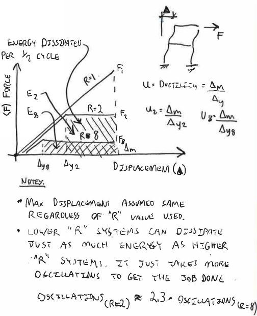
I made you a spiffy sketch mes7a (below). If you study it carefully, it will reveal a fundamental principle that is built into modern seismic design provisions but isn't discussed much. That principle ss called the Equal Displacement Principle. If you google that term, you'll turn up a ton of related explanatory material.

The gist of the equal displacement principle is that a building lateral system will experience approximately the same amount of displacement under design seismic excitation regardless of the level of ductility built into the system. Whether it's R=2 or R=8, the total displacement is the same. The only difference is that an R=8 system would experience more of that displacement as plastic deformation and less as elastic deformation.

In the end, an R=2 building will dissipate just as much seismic energy as an R=8 building. It will just take more oscillations to do it. In the example shown below, the R=2 building wold require 2.29 times as many oscillations to dissipate the same amount of energy as the R=8 building.

The take away from all this is that, fundamentally, a low R building is no more dangerous seismically than a high R building so long as the design seismic forces are adjusted appropriately. Of course, if your local building code flat out prohibits low ductility systems, then that is another matter. The one difficulty with low R design is that it's very difficult to predict seismic loads accurately. And high R systems tend to be more forgiving. That's why some codes prohibit low R systems in high seismic regions.

Sometimes essential services buildings in high seismic regions will be intentionally constructed using low R systems. That is done because a properly designed low R system can be expected to suffer the least amount of damage during an earthquake. R=8 means that a building doesn't fall down but it will be nearly destroyed after a design seismic event. Such a building may have compromised vertical transportation and mechanical systems and may need to be demolished rather than re-occupied. In theory, an R=1 hospital should never even have to close its doors.

In New Zealand, they're beginning to question whether or high ductility is even a good idea. Poor Christchurch was damaged so badly that they even considered relocating the city rather than attempt to repair all of the damaged infrastructure. The modern trend towards performance based design is taking us in this direction as well. Owners of buildings where the contents are far more valuable than the building (data centres etc) don't want their facilities to have to weather R=8 damage.

CAPTURE_hefknz.jpg


I like to debate structural engineering theory -- a lot. If I challenge you on something, know that I'm doing so because I respect your opinion enough to either change it or adopt it.
 
The take away from all this is that, fundamentally, a low R building is no more dangerous seismically than a high R building so long as the design seismic forces are adjusted appropriately. Of course, if your local building code flat out prohibits low ductility systems, then that is another matter. The one difficulty with low R design is that it's very difficult to predict seismic loads accurately. And high R systems tend to be more forgiving. That's why some codes prohibit low R systems in high seismic regions.

Our codes copy everything 100% from ACI. But building officials engineers don't focus on differentiations between low and high R so they just gave approval for gravity load. Therefore designers in my place are exempted from any liability should the building suffer from any seismic activity.

Anyway.

LmhgiU.jpg


For Low R building with detailing that matches special moment frames.. like my structure which matches the detailing of special moment frames. Then it's still called Low R because the column are more rigid.. isn't it. Failure mode of ordinary moment frames are shear failure. So with my shear detailing of columns at 70mm o.c. at upper and lower part, then the effect is more capacity elastically? Now the question is.. you said you can push special moment frames 4 times more than ordinary moment frames. But what happens if the ordinary moment frames has shear detailing just like SMF and even more flexural capacity than SMF (the paper above says SMF has fewer flexural rebars so it can yield taking part of the seismic force).. then can the OMF be pushed 4 times too and perform like SMF?

Also when you are building a say 4 storey building with designed R=8.. and you just do actual 2 storey.. is it like turning the R into 5? In details, the effect of is like if you build the full R-8 compliant 4 storey. The columns became flexible enough (R=8).. but if you just finish 2 storey, then the columns became rigid in comparison with other 2-storey (then R=5). Is this concept right? This means if I finish the designed 4 storey. Then it becomes bonafide special moment frames? If I just finished 2 out of 4 storey. It's become ordinary moment frames (as far as flexibility is concerned) or no difference at all?
 
You're heading off the rails here mes7a. Think of it like this:

1) If all parts of your building were SMF compliant, we wouldn't be having this conversation.

2) Some parts of your building are SMF compliant (columns) and others are not (footing connections).

3) Because not all parts of your building are SMF compliant, you do not have an SMF (mike's point).

4) What you're left with could be conceived of as an OMF or IMF in which some members, but not all, posses more ductility than they require in order to satisfy OMF/IFM requirements. Good for them.

5) In no case would SMF detailing cause an otherwise acceptable member to be unsuitable for use in an OMF/IMF.

mes7a said:
then can the OMF be pushed 4 times too and perform like SMF?

No. Once drift reached the OMF limit, the portions of your structure that are not SMF compliant would fail. Your frame is, essentially, only as ductile as the least ductile component.

I like to debate structural engineering theory -- a lot. If I challenge you on something, know that I'm doing so because I respect your opinion enough to either change it or adopt it.
 
You're heading off the rails here mes7a. Think of it like this:

1) If all parts of your building were SMF compliant, we wouldn't be having this conversation.

2) Some parts of your building are SMF compliant (columns) and others are not (footing connections).

3) Because not all parts of your building are SMF compliant, you do not have an SMF (mike's point).

4) What you're left with could be conceived of as an OMF or IMF in which some members, but not all, posses more ductility than they require in order to satisfy OMF/IFM requirements. Good for them.

5) In no case would SMF detailing cause an otherwise acceptable member to be unsuitable for use in an OMF/IMF.

Ok. Since there is insufficiency (like the footing connection). Then if I jus finished 2 storey out of 4. The OMG part would be stronger and has more elasticity than building the full 4 storey right?

Because if the effect is significant. I just just retain the 2 storey and treat it as very strong OMF with more elastic limit than a full 3 or 4 storey OMF that is weaker elastically.

But generally it's really true that if you build just half of a special moment frame building storeys.. the columns would be more rigid for the design and become an OMF?
 
Think of it like this:

1) any given level of your building is capable of a certain, safe, total lateral displacement of which part is elastic and part is inelastic. Lopping off stories doesn't change this.

2) lopping off stories will result in your building experiencing less lateral seismic displacement. This is the only thing that lopping off stories will affect.

3) with less demand for seismic lateral displacement, there is a greater likelihood that the displacement demand (#2) will not exceed total displacement capacity (#1). This is the most fundamental way of stating the condition of seismic safety.


I like to debate structural engineering theory -- a lot. If I challenge you on something, know that I'm doing so because I respect your opinion enough to either change it or adopt it.
 
Think of it like this:

1) any given level of your building is capable of a certain, safe, total lateral displacement of which part is elastic and part is inelastic. Lopping off stories doesn't change this.

What I'm saying is simply this. Imagine you are building a special moment frame 30-storey building with 2 meters diameter columns at ground floor.. but you ran out of budget and only build 2-storey out of it. The 2 meters wide columns sure won't be called special moment frame, isn't it? because it won't be flexible. So in this case.. do you called the 2 storey building (out of 30-storey design) ordinary moment frame or special moment frame?.
 
mes7a said:
The 2 meters wide columns sure won't be called special moment frame, isn't it? because it won't be flexible.

No, the columns would still be SMF compliant. SMF is about ductility, not flexibility. Column ductility is a function of the column properties and nothing else.

mes7a said:
. do you called the 2 storey building (out of 30-storey design) ordinary moment frame or special moment frame?.

I would call it a grossly oversized SMF unlikely to ever see lateral displacement ductility demands exceeding those associated with OMF.

I like to debate structural engineering theory -- a lot. If I challenge you on something, know that I'm doing so because I respect your opinion enough to either change it or adopt it.
 
Status
Not open for further replies.

Part and Inventory Search

Sponsor