Continue to Site

Eng-Tips is the largest engineering community on the Internet

Intelligent Work Forums for Engineering Professionals

  • Congratulations waross on being selected by the Eng-Tips community for having the most helpful posts in the forums last week. Way to Go!

Horizontal Trussing Threshold for Roof Diaphragm 3

Status
Not open for further replies.

mes7a

Structural
Aug 19, 2015
163
Hi,

How rigid must be the horizontal trussing in a roof before it can be considered a full fledge diaphragm? When the structure was constructed. They use 0.5x0.5 meter column from foundation all the way to third floor (it was designed for 4 storey).. but we decided now to build up to 3 storey only and plan to use thin metal roof to shed rain at gutter at side.

I know there must be a threshold in the horizontal trussing before the huge columns can become a diaphragm. For example. If you merely use a pole connecting the columns.. it can't be considered a diaphragm. Is it?

Also must the rafters be straight horizontal.. how about a bent gable rafter with apex at middle.. can a bent rafter create a diaphragm.. again what is the threshold of the rigidity? The pole is also rigid.. must it be certain strength compared to the huge columns?

Thank you.
 
Replies continue below

Recommended for you

Thanks Kootk. This would explain my paranoia.


"With a magnitude of 7.2, the study found that 170,000 residential houses will collapse, 340,000 residential houses will be partly damaged, 34,000 persons will die, and 114,000 persons will be injured."

My building is less than 10 kilometers away from the fault line. Our capital would get back to the stone age should the west valley quake occur.

So my paranoia is really vigilance.

In your building design... do you compute for the soil/rock filtering of accelerations or waves? because if it matches the building fundamental period.. the resonance can increase the seismic force.. as estimate.. how many times do you think is the effect should there be resonance of soil/rock acceleration and building period?
 
I would have to rely on geotechnical engineers for guidance with the soil resonance. I'd recommend posting this question in that section of the forum. It's not considered explicitly in routine design. To some extent, it's built into the seismic site classification system I believe.

I like to debate structural engineering theory -- a lot. If I challenge you on something, know that I'm doing so because I respect your opinion enough to either change it or adopt it.
 
Holy smokes!

"It is imperative Cunth doesn't get his hands on those codes."
 
No, the columns would still be SMF compliant. SMF is about ductility, not flexibility. Column ductility is a function of the column properties and nothing else.

Professor Kootk. Thanks for this very important distinction or clarifications. Because in the article "Seismic Design of Reinforced Concrete Special Moments Frames: Guide for Practicing Engineers". it is stated that:

"Both strength and stiffness need to be considered in the design of special moment frames. According to ASCE 7, special moment frames are allowed to be designed for a force reduction factor of R = 8. That is, they are allowed to be designed for a base shear equal to one-eighth of the value obtained from an elastic response analysis. Moment frames are generally flexible lateral systems; therefore, strength requirements may be controlled by the minimum base shear equations of the code."

This gave me the impression for a couple of years that special moment frames is about flexibility.

In Wight book. It is stated:

"As discussed previously, more ductile structural systems can be safetly designed for lower seismic forces than systems with limited ductility." The Equal Displacement Principle is shared there as:

qHDzvy.jpg


But then they say not to make the lateral system so stiff so as not to attract more seismic forces. Isn't this the same as flexibility? Or can you really make the columns much bigger and don't care about the seismic force it can attract because shear can easily be handled by columns via lateral ties.. this means as long as the columns have enough ductility.. then it's ok to make it bigger.. and have at least more elastic reserve before ductile response initiated and this won't take away the SMF label. Is this what you were pointing out?
 
Stiffer systems often do attract more seismic load. That is indeed true. However, ductility and stiffness do not always vary in unison. Just because something is stiff, that doesn't mean that it isn't also ductile. You can have both very stiff SMF and very flexible SMF. And the same is true of OMF.

I like to debate structural engineering theory -- a lot. If I challenge you on something, know that I'm doing so because I respect your opinion enough to either change it or adopt it.
 
Stiffer systems often do attract more seismic load. That is indeed true. However, ductility and stiffness do not always vary in unison. Just because something is stiff, that doesn't mean that it isn't also ductile. You can have both very stiff SMF and very flexible SMF. And the same is true of OMF.

Ok. And while talking about the article read by thousands: "Seismic Design of Reinforced Concrete Special Moments Frames: Guide for Practicing Engineers". It is mentioned in the foundation part that:

"Modeling pinned restraints at the base of the columns, Figure 4-1 (a), is typical for frames that do not extend through floors below grade. This assumption results in the most flexible column base restraint. The high flexibility will lengthen the period of the building, resulting in a lower calculated base shear but larger calculated drifts. Pinned restraints at the column bases will also simplify the design of the footing. Where pinned restraints have been modeled, dowels connecting the column base to the foundation need to be capable of transferring the shear and axial forces to the foundation."

But you mentioned special moment frames footing must be fixed to create complete mechanism. Why would the article talked about pinned restrains which won't create any complete mechanism (plastic hinges at the column bases in the footing)?

Maybe because when your column base form plastic hinges.. the building is no longer repairable. So some engineers can get away with pinned footing restrained? What do you make of it? Why would the article mentioned about pinned footing if it is not part of Special Moment Frame which is their main topic?
 
You only need column base plastic hinges to form a mechanism if you have modelled your column bases as fixed. The whole idea is to create a true pin at the column base. If you started off with a pinned column base, this step is already complete.

I disagree with the referenced paper regarding whether or not column bases at grade level pad footings should be modelled as pinned. My opinion is that typical construction details at column/firing joints produce considerable fixity that should be accounted for. That fixity must be overcome before mechanism formation is complete.

I like to debate structural engineering theory -- a lot. If I challenge you on something, know that I'm doing so because I respect your opinion enough to either change it or adopt it.
 
The take away from all this is that, fundamentally, a low R building is no more dangerous seismically than a high R building so long as the design seismic forces are adjusted appropriately. Of course, if your local building code flat out prohibits low ductility systems, then that is another matter. The one difficulty with low R design is that it's very difficult to predict seismic loads accurately. And high R systems tend to be more forgiving. That's why some codes prohibit low R systems in high seismic regions.

You mentioned above "some codes prohibit low R systems in high seismic regions". All I heard of or read is ordinary moment frames can't be used in high seismic regions (our country copied the ACI codes word by word). What particular codes don't forbid them? I want to read about them.

I think an R=1 is something that can respond elastically like nuclear power plants. So these vital installations use R=1 and ordinary moment frames, huh?
 
I don't have answers to either of those questions mes7a. Perhaps other forum members will be able to comment.

I like to debate structural engineering theory -- a lot. If I challenge you on something, know that I'm doing so because I respect your opinion enough to either change it or adopt it.
 
I don't know what codes don't forbid OMF in high seismic.

I don't think using R=1 necessarily means an elastic design. There is a method to keep critical structures close to elastic in an EQ, but it involves a time-history suite and R=0.85 if I remember correctly. I will try to dig up the reference.
 
Stiffer systems often do attract more seismic load. That is indeed true. However, ductility and stiffness do not always vary in unison. Just because something is stiff, that doesn't mean that it isn't also ductile. You can have both very stiff SMF and very flexible SMF. And the same is true of OMF.

"Stiff SMF" as you mentioned above may no longer have R=8. There must be terms to refer to Stiff SMF that have R=5. Or maybe Stiff SMF must be called IMF that is ductile enough to have adaptive R from 5 to 8?

Also I read this:


"They concluded that for a structure of a natural period less than 0.2 second (short period structures), the ductility does not help in reducing the response of the structure. Hence, for such structures, no ductility reduction factor should be used."

Structure having natural period of 0.2 is about 2 to 3 storey building. So it's possible such buildings are so stiff that strength must be priorized? Because if you make 2 storey building so flexible.. it may be in danger of P-delta effect or sorta.
 
Dear Kootk..

Let me share something which have been bothering me for years and related to my massive inquiries about moment frames and lessening drift and beam rotations.. it's because my beams were not really special moment frames. Here's why.

In our country. Our designers use stirrup spacing not from calculations but from memorization of 10mm at 4 inch o.c. and larger spacing as it goes to midspan.. or from uniform load.

When the designers design my girder with secondary beam framing into it. They use stirrups spacing of uniform load. Later I told him after construction is finished that his spacing is wrong (as commented by others). Then he realized it's true. The shear should not be from uniform load but instead look like this:

JsXYpd.jpg


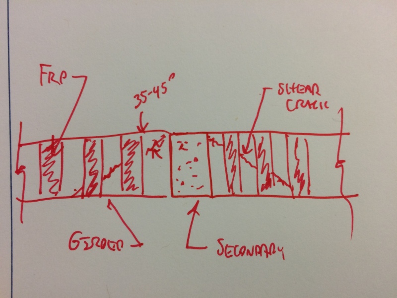
Anyway. For secondary beam framing into primary. Does the shear cracks look like the following?

LMSaga.jpg


Indian structural engineers I consulted said the cracks occur 2D away from the point where secondary frame into primary.
Is it true? My fear is it may be closer to the center.

This is another reason I didn't continue the top floor.. to lessen story shear below.. and hoping the bigger columns can prevent drift and beam rotations. Their computations show the midspan is good for gravity loads. And they recommended carbon fiber for the missing capacity for cyclic loading. The designers are so convinced the carbon fiber can make up for insufficient stirrups at midspan but I read carbon fiber doesn't work much.

So my beams and footing connection are not special moment frames. My hope is the bigger columns and lesser storey can create the scenario where the columns can become OMF or IMF with ductility and drifts would be less enough to avoid cyclic loading in the beams.

Again my main question is. During cyclic loading.. would the cracks at midspan where secondary beam frames into it be 2D away from midspan or nearer? What is your experience of this? I got nervous for it for months about it a year back and still now.
 
Your concern is whether or not the shear cracks will be crossed by the FRP stirrups, right? If so then, yes, your cracks should emanate from the top of the beam and emanate downwards to cross the FRP stirrups.

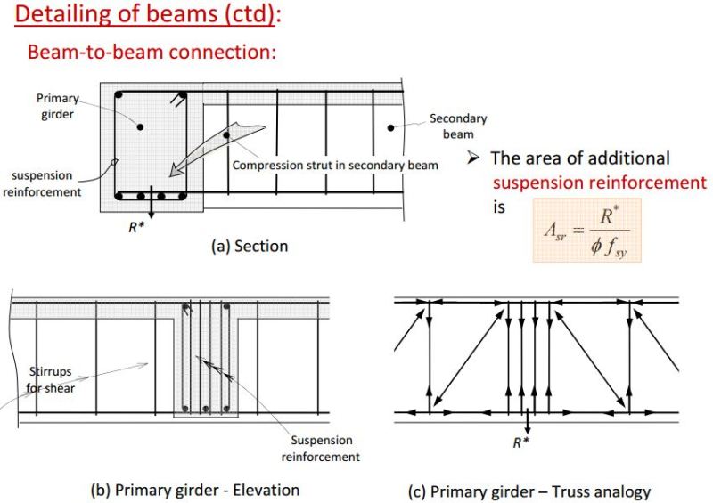
The shear detailing of your beam would satisfy ACI requirements. In my jurisdiction, however, the practice is to provide "hanger" reinforcement stirrups right behind the supported beam. See the sketch below. This practice has always been debatable, however, as zillions of beams get cast in the US without hanger (suspension) reinforcement and nothing terrible ever seems to happen as a result.

Capture1_bbout0.jpg


Capture2_vcxy8l.jpg


I like to debate structural engineering theory -- a lot. If I challenge you on something, know that I'm doing so because I respect your opinion enough to either change it or adopt it.
 
Your concern is whether or not the shear cracks will be crossed by the FRP stirrups, right? If so then, yes, your cracks should emanate from the top of the beam and emanate downwards to cross the FRP stirrups.

But FRP doesn't work. I have spent over 2 months reading about it 2 yrs ago. It can debond from surface before it breaks.. so I don't trust it. Instead I trust on the original stirrups. If the cracks angle is like you described.. some of the original rebar stirrups can cross it. But the problem is that in seismic movement and cyclic loading.. the plastic hinge can form at midspan and the shear cracks can be anywhere. See:


cNU1hl.jpg


This is for beam with uniform span in cyclic loading. Do you have picture of how it looks like when a secondary beam frames into the primary and it is in seismic cyclic loading? Where would the plastic hinge form? Right at midspan? Then the lack of original rebar stirrups worry me at times.

This is why I'm hoping not building the 4th storey would lessen storey shear below and make the building stiffer and just save it.

Anyway. Don't worry. We would stop at the 100th message. Lol. I know it's a long thread. And at 100th message. I'd stop and reflect about it all.
 
In my jurisdiction, however, the practice is to provide "hanger" reinforcement stirrups right behind the supported beam. See the sketch below. This practice has always been debatable, however, as zillions of beams get cast in the US without hanger (suspension) reinforcement and nothing terrible ever seems to happen as a result.

About hanger reinforcement, I actually got worried about it 2 years ago and discussed it with indian structural engineers. The figure is from "Leonhardt, F. and E. Mönnig 1977, Vorlesungen uber Massivebau, Dritter Teil, Grundlagen zum Bewehren im Stahlbetonbau, Dritte Auflage, Springer-Verlag, Berlin, p. 246"

fzZfiM.jpg


It seems when your secondary beam shear is more than Vc and the it can suffer diagonal crack that you really need to worry much. The drawing of the compression fan (from Mcgregor presentation of the 1984 Canadian Concrete Code 6-29)

nPy8Kc.jpg


It seems internal Hanger stirrups are only required if V (shear) at the end of the supported beam is beyond a certain threshold that can cause diagonal cracking. Dolan Et Al mentioned "Hangers will also be unnecessary if the factored beam shear is less than 0.85Vc (as is usually the case for one-way joists, for example), because in such a case diagonal cracks would not form in the supported member. The predictions of the trust model would thus not be valid, and the reaction would be more nearly uniform through the depth."

Another author Mcgregor stated " These provisions can be waived if the shear, Vu2, at the end of the supporeted beam is less than 3*sqrt(fc')bd, because inclined cracking is not fully developed at this shear."

But then it seems you are talking about noncrack secondary beam with the primary needing to transfer the reaction up.

The stirrups can equilibrate the top and bottom bars near midspan.. so it's my hope 2 years ago the beam won't just fall down. But then during reverse seismic loading (up and down). It may stress it. One more reason I want to lessen seismic load of building.

Thanks for reminding it. Because I have about 1-2 inches of concrete topping in the roofdeck now above my 2nd floor to make rain flow to drains.. But since the third floor will be covered by light wall and light roof soon. I think I'll remove all the 1-2" of concrete topping above waterproof to lessen the SD load and compensate for missing hanger reinforcement.

Anyway. In case I'll build another building. I'll surely have massive internal hanger stirrups to complete the truss analogy (stirrups only cost little so most plans must include it).
 
Kootk.. I had difficulty sleeping last night because something kept bothering me. I have thought of it 2 years ago but it's coming back to me.

In the picture you showed above:

Flupkm.jpg


The secondary bottom bars are resting above the primary bottom bars. There are 4 bottom bars which matches my girder's bars too.

My worry is could the bottom bars just fracture from the weight of the secondary beams (since there is lack of hanger reinforcement you mentioned.. although I had one internal hanger inside (10mm hoop). How do you exactly compute for the bar sideway tensile strength.

Using area of 20mm rebar as 0.000000314 and tensile strength of 414 MPA.. if you multiply the two, you come up with 130 kN. If there are 4 bars.. total capacity is 520kN? But it is sideway. How would you convert it to sideway capacity of a rebar?

Do you think all the load are being concentrated on the 4 bottom bars of the primary girder beam? If not.. how many percentage roughly? How do you analyze it?

My equivalent axial load of 2 secondary beam framing into the primary girder is 350kN.. Do you divide this by two to distribute it to the 2 bottom bars of the secondary beams framing into the primary?

Let's wrap it up when we reached message #100. Lol..
 
ACI Vc shear procedures encompass a variety of things that contribute to shear resistance including friction at the compression block, aggregate interlock, and longitudinal bar dowel action. While the dowels add something to the shear capacity for certain, I wouldn't want to rely on them as the sole means of shear transfer.

mes7a said:
Using area of 20mm rebar as 0.000000314 and tensile strength of 414 MPA.. if you multiply the two, you come up with 130 kN. If there are 4 bars.. total capacity is 520kN? But it is sideway. How would you convert it to sideway capacity of a rebar?

You've used dowel tensile strength here when the relevant parameter would be dowel shear strength. In reality, it isn't the rebar that fails in dowelled connections. Rather, it is the concrete surrounding the rebar. In this case, the girder concrete below the dowels might spall off. There would be dowel bending at play as well but there's probably no need to get into that.

I like to debate structural engineering theory -- a lot. If I challenge you on something, know that I'm doing so because I respect your opinion enough to either change it or adopt it.
 
You've used dowel tensile strength here when the relevant parameter would be dowel shear strength. In reality, it isn't the rebar that fails in dowelled connections. Rather, it is the concrete surrounding the rebar. In this case, the girder concrete below the dowels might spall off. There would be dowel bending at play as well but there's probably no need to get into that.

Why do you call it dowelled connection. I'm talking about the 4 main longitudinal bars of the primary girder beam. The reactions from the secondary beam is towards the bottom as it framed into the primary beam. This is why you mentioned about hanger reinforcement.. to carry the force to the upper longitudinal bars of the primary girder.

Now i'm not talking about hanger reinforcement to transfer the force from bottom of girder to top.. but the shear strength of the longitudinal bar itself (it can fracture when it can no longer take the axial load, isn't it?). What is the percentage of the shear strength of the bar compared to its tensile strength? I heard it is 3/4 or 1/2? You mean the reactions from the secondary beams don't focus on the girder bottom rebars but still carried in the whole section of the concrete? To what extend.. how many percentage approx. does the rebar carry the whole axial load of the secondary beams?
 
mes7a said:
Why do you call it dowelled connection.

What you've described, in my mind, is a dowelled shear connection.

mes7a said:
What is the percentage of the shear strength of the bar compared to its tensile strength? I heard it is 3/4 or 1/2?

0.75 Fy at ultimate; 0.58 Fy at yield.

mes7a said:
To what extend.. how many percentage approx. does the rebar carry the whole axial load of the secondary beams?

I don't know the ratios I'm afraid.

I like to debate structural engineering theory -- a lot. If I challenge you on something, know that I'm doing so because I respect your opinion enough to either change it or adopt it.
 
0.75 Fy at ultimate; 0.58 Fy at yield.

I don't know the ratios I'm afraid.

About 2 years ago I was discussing it with some indian structural engineers in this indian thread:


Someone there said "The secondary beam reaction will be cusing a crack on main bar if the main bar can not resist it and if it has not been provided with extra stirrups on either side at a distance "d" and in addition as one of the sefians posted crank or bent up bar is provided."

Kootk.. do you believe it is possible the secondary beam reaction can cause a crack in the main bottom bar? Do you compute it at 0.75 Fy?

But the joint being monolithic.. hopefully the concrete can carry some load.. would it.. how do you analyze this in your design?
 
Status
Not open for further replies.

Part and Inventory Search

Sponsor