Hi, I've been trying to figure out how to correctly define a hole in relation to a face but all the literature seems to be for fixed gauge pins. This isn't what I want though, I'll try explain...
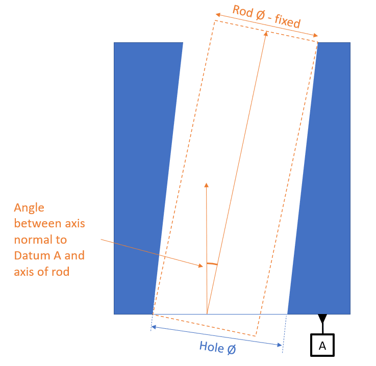
The hole is perpendicular to the face (which is our datum feature).
The hole is there to guide a rod, so I need it to be: a) perpendicular to the face and b) a good fit on the diameter. The rod can be thought as loose, with the hole being the only thing touching it.
I want the worst case angular offset between the rod axis and the axis perpendicular to the face to be my limiting condition.
Now the tolerances on this is very tight so I would like to do something similar to a MMC between the hole diameter and the perpendicularity between the hole and face.
So a bad perp could be compensated for by a tight diameter and vice versa.
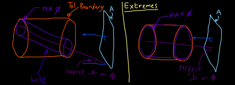
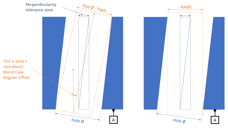
However MMC seems to be based around the RAME, where I would like to base it around the... well I don't know if there's a term for it, the opposite of the RAME?
(by RAME I mean the largest diameter cylinder that is perpendicular to datum A that will fit in the hole - see below)
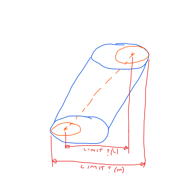
I want a fixed diameter cylinder that sits in the hole in the position with the worst possible perpendicularity.
I have a way of inspecting this using the CMM and some excel code but I'm struggling to correctly define it on the drawing.
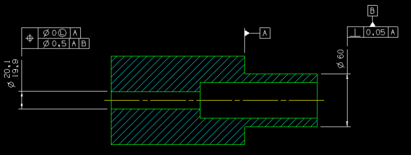
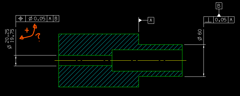
I'm considering using position instead of perp on the hole (see image below). Or maybe runout is what I want... though you can't use MMC with it, tho I can imagine an offset but straight hole failing this, maybe a position to control the axis position, and a runout to that axis (and perp to A)...
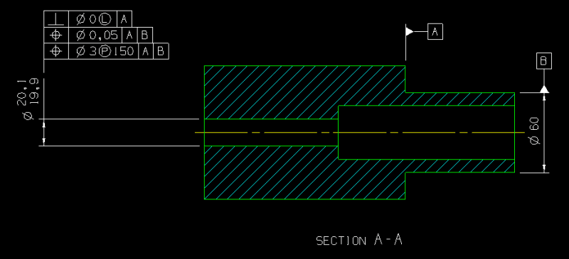
Here's a rough drawing with the basic set up (pay no heed to the values)
Maybe it's not possible and I'll have to just stick a note on trying to explain it the best I can with the tols opened enough to allow individual features to pass in all scenarios with the ultimate bottle neck being the formula result. Although I feel this isn't a particularly niche scenario and there should be a way to define this.
If you need any clarity let me know. Thanks")
The hole is perpendicular to the face (which is our datum feature).
The hole is there to guide a rod, so I need it to be: a) perpendicular to the face and b) a good fit on the diameter. The rod can be thought as loose, with the hole being the only thing touching it.
I want the worst case angular offset between the rod axis and the axis perpendicular to the face to be my limiting condition.
Now the tolerances on this is very tight so I would like to do something similar to a MMC between the hole diameter and the perpendicularity between the hole and face.
So a bad perp could be compensated for by a tight diameter and vice versa.
However MMC seems to be based around the RAME, where I would like to base it around the... well I don't know if there's a term for it, the opposite of the RAME?
(by RAME I mean the largest diameter cylinder that is perpendicular to datum A that will fit in the hole - see below)
I want a fixed diameter cylinder that sits in the hole in the position with the worst possible perpendicularity.
I have a way of inspecting this using the CMM and some excel code but I'm struggling to correctly define it on the drawing.
I'm considering using position instead of perp on the hole (see image below). Or maybe runout is what I want... though you can't use MMC with it, tho I can imagine an offset but straight hole failing this, maybe a position to control the axis position, and a runout to that axis (and perp to A)...
Here's a rough drawing with the basic set up (pay no heed to the values)
Maybe it's not possible and I'll have to just stick a note on trying to explain it the best I can with the tols opened enough to allow individual features to pass in all scenarios with the ultimate bottle neck being the formula result. Although I feel this isn't a particularly niche scenario and there should be a way to define this.
If you need any clarity let me know. Thanks