Eng-Tips is the largest engineering community on the Internet

Intelligent Work Forums for Engineering Professionals

How to draw a 2-position selector switch and its contacts? (IEC world) 4

Status
Not open for further replies.

JuanBC

Electrical
Nov 28, 2017
141
0
0
AR
Hi,

I would like your opinion on how to correctly draw a 2-position selector-switch (Hand-Automatic) under "IEC world". Should I draw both contacts opened and the switch neither in "H" nor "A"?

Both contacts themselves should be purchased "normal open" (NO) but one must be placed in such a way that it closes when the selector switch is in "H" and the other that should close when it is in "A"

Please see attached example

Thanks!

JBC
.......
"The more I read, the more I acquire, the more certain I am that I know nothing"
 
 http://files.engineering.com/getfile.aspx?folder=e88a0b38-2e1c-4b23-b025-8bfc7936e161&file=2_position_selector_switch.png
Replies continue below

Recommended for you

A Is wrong as it shows incorrect physical movement. It's showing both contacts have to operate when the "operator" (the knob) is turned clockwise. (BTW That was my first failed drawing!)

E is also wrong as it clearly denotes a Normally Closed contact is involved which is not the case.

D is the correct one IF this is a two position switch.

C is the correct one IF this is a three position switch - EXCEPT! In this case the truth table is wrong. It needs a third center column showing the center position with NO 'X's.

Keith Cress
kcress -
 
Yep, I agree with Keith. Option E may lead to a bad purchase of equipment needed.

The selector switches being used have only two positions (Hand or Automatic - both "latched")

What I do not like about "option D" is that I am drawing the switch in neither position H nor A (see dashed line on the big "V"), and we are used to draw schematics in "pasive state"

Conclusion: fuc* IEC
 
Yes, and this is a pain in the ass for me as a OCD ahah

JBC
.......
"The more I read, the more I acquire, the more certain I am that I know nothing"
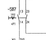
 
By itself the contact block is normally open but when assembled to the operator it becomes normally-open-held-closed, or functionally normally closed.
In the absence of a symbol for normally-open-held-closed we are faced with ambiguity.
Option D is correct for a three position switch but may be misleading for a two position switch.
The position that the contacts are in in D does not correspond to any entry in the truth table.
This is not to argue, but to point out the ambiguity and suggest the need for a descriptive footnote.

Bill
--------------------
"Why not the best?"
Jimmy Carter
 
Bill, I agree with you on almost everything except the following:

waross said:
suggest the need for a descriptive footnote

In my short experience in engineering I realized that most of the people (sadly) do not read notes on a schematic. I think although messy, it is better to direct write it next to the symbol (or at least use an asterisk)

JBC
.......
"The more I read, the more I acquire, the more certain I am that I know nothing"
 
The drawings that I most often see would have the words See Note #1 next to the symbol on the drawing. If that direction is not included, then I agree with your comment.


Bill
--------------------
"Why not the best?"
Jimmy Carter
 
Hello Gentleman

Here is a diagram common to all our German equipment.


getfile.aspx

 
That is showing a three position switch.
Again, possible confusion.
The two position switch does not have a position where both contacts are open as shown.

Bill
--------------------
"Why not the best?"
Jimmy Carter
 
A "two position switch" will need to be expressed as one or the other contacts closed. I would have it in the "Auto" position
and have what ever be it a contactor or another switch which completes the circuit in the open position to indicate a non-energize state.

Chuck
 
Chuck that doesn't seem to be available in IEC land. You have to just consider the schematic symbol as being a snapshot of the switch while it's in-motion on its way to a position the final outcome being shown as the dashed lines of the "V" with a two position showing both as dashed possibilities of "ON" switches.

Keith Cress
kcress -
 
I mean no offence however, logical clarity is lacking in this design a two position switch must be in one or the other positions while I am probing during troubleshooting the circuit. But I always come here for advice when I need help so possibly missing the point, forgive me for thinking binary. [banghead]

Chuck
 
OP said:
See attached. IMO, option "A" is the clearest of all
Link
I still think option "E" most clearly demonstrates the action of the switch as installed.
I think that a lot of our confusion has been caused by a misleading catalogue description.
I suggest that if we lack a symbol to show normaly-open-held-closed then a normaly closed symbol most clearly describes the action of the circuit.
Remember that one purpose of the diagram is to aid in troubleshooting.
Included in the note that we discussed may be a bill of material that calls up the switch with the confusing description. That way you get the switch that you wish to use and the field technician has a drawing that he can understand.

Two position switch versus a three position switch.
I can understand the use of a Hand/Automatic switch in an application where the designer does not want the possibility that a Hand/Off/Automatic switch may be forgotten in the off position.

Bill
--------------------
"Why not the best?"
Jimmy Carter
 
Chuck,

You're not missing anything. It is simply a horrible symbol.

By a perverse twist of fate I'm actually drawing up circuit schematics myself this week to bail out another group who forgot to request any drawings from Engineering before sending a job to the installation team, who are now sending us variation notices for stoppage time. I am using the old British Standard symbol because we all understand it, even if IEC says otherwise.
 
:) Bill..

The "E" left switch is precisely the IEC symbol for a N.C. switch. You cannot use that anywhere in Any Ville NEMA or IEC or ? without mass confusion ensuing. Right from the start you'll have people buying the N.C. switch blocks to jack onto the back of the ON-ON operator. Of course that would then make the switch be open when in that position. Then the rocket will launch while they're disconnecting the fuel hoses and... poor outcomes would be expected.

Keith Cress
kcress -
 
Hi Keith. You are inadvertently making my point.
Back in the day when I was doing a lot of control work, ordering parts, designing new circuits, repairing, troubleshooting etc., All of our selector switches used contact blocks with one set of normally open and one set of normally closed contacts.
Then came the contact blocks with only one set of contacts.
In some product lines the single contact blocks were interchangeable with the two contact blocks.
Our diagrams always showed the contacts in the as installed or as assembled position.
It was not unusual to have an operator which held a normally open contact closed in normal operation.
It was up to the person ordering the parts to determine whether an operator would reverse the action of the contact block.
If I go to a different brand and order a switch with two normally open contacts, I will many times get a switch with two normally open contacts, just as the drawing shows. Not going to work.
Also, to show two normally open contacts presupposes that an electrician working on the circuit has pre-knowledge that one of the normally open contacts is actually normally closed.
I have had to assemble selector switches that reversed the action of a set of contacts. The drawing always showed the action of the selector switch as assembled.
It is up to the person buying or assembling the selector switch to select the proper contacts so that the action is as needed, regardless of the configuration of the contact block before it is mated to the operator.
By the way, a common contact block offered by more than one manufacturer back in the day was stackable.
The second contact block could be mounted in tandem where it may be open in the normal position or mounted to the back of the first contact block where held closed in the normal position.
You MUST show the action of the devices AS ASSEMBLED.

Bill
--------------------
"Why not the best?"
Jimmy Carter
 
Given the info of a 2-position switch using 2 x N/O contacts, A or D are the only possible correct drawing.

We use a drawing like Keith showed first, except the lines would be above the circles. We always use the line above the circles for a N/O contact block and the line below and touching the circles for a N/C contact block. We DO NOT draw the switch contacts as installed with the switch in one of the positions. We have tried it various ways and drawing the contacts as the type of block is the least confusing. The way we draw it, it shows the type of contact blocks and when the contact is closed. So, all the info you need about the switch is on the switch drawing.

Translating this to IEC world, the same logic applies meaning A or D are the only possible choices. Since I like to see the same symbol used for the same type of contact block, I would use drawing A over drawing D. Mirroring the contact symbol as in drawing D could be confusing to someone.

B and D show a center position so they are wrong. E shows a N/C contact so it is wrong. Sorry Bill, but E would only be right if a N/C contact block is being used on the switch operator and the OP specified that 2 x N/O contacts are being used.
 
Status
Not open for further replies.
Back
Top