Continue to Site

Eng-Tips is the largest engineering community on the Internet

Intelligent Work Forums for Engineering Professionals

  • Congratulations pierreick on being selected by the Eng-Tips community for having the most helpful posts in the forums last week. Way to Go!

How to draw a 2-position selector switch and its contacts? (IEC world) 4

Status
Not open for further replies.

JuanBC

Electrical
Nov 28, 2017
141
Hi,

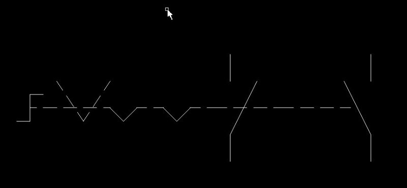
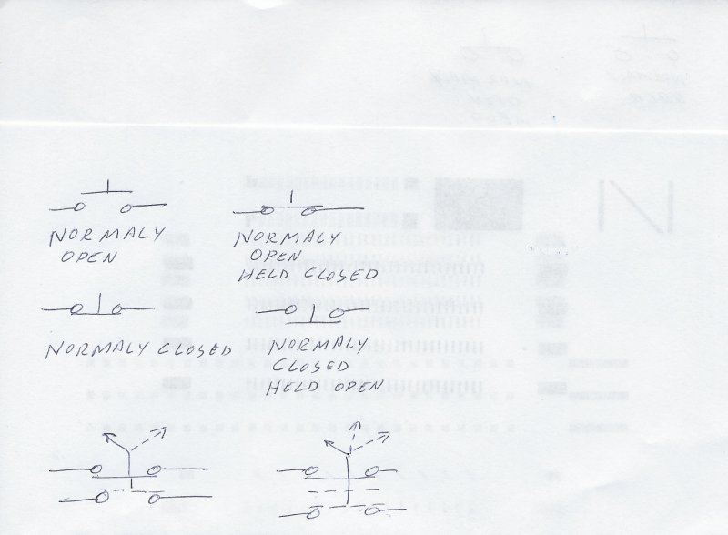
I would like your opinion on how to correctly draw a 2-position selector-switch (Hand-Automatic) under "IEC world". Should I draw both contacts opened and the switch neither in "H" nor "A"?

Both contacts themselves should be purchased "normal open" (NO) but one must be placed in such a way that it closes when the selector switch is in "H" and the other that should close when it is in "A"

Please see attached example

Thanks!

JBC
.......
"The more I read, the more I acquire, the more certain I am that I know nothing"
 
 http://files.engineering.com/getfile.aspx?folder=e88a0b38-2e1c-4b23-b025-8bfc7936e161&file=2_position_selector_switch.png
Replies continue below

Recommended for you

Can't say if this is IEC or not but it's the only easily understandable panel-twist-switch symbol I've ever seen. It's also easily extendable to multi-position and to more than 2 contacts. You can just keep stacking them up. Multiple positions (more than 3) are easily accommodated.

The dotted line shows the switch position associated with the contact that closes in that switch position. Note that you can actually have a drum switch where an operator position actuates several separate contacts at once by adding more "x"s where needed.


Switchs_vyf293.jpg


Keith Cress
kcress -
 
The AutoCAD Electrical library has example IEC symbols that can be found here. Don't forget to add the second contact.

xnuke
"Live and act within the limit of your knowledge and keep expanding it to the limit of your life." Ayn Rand, Atlas Shrugged.
Please see FAQ731-376 for tips on how to make the best use of Eng-Tips.
 
In xnuke's link try an HSS122R above an HSS21.

Bill
--------------------
"Why not the best?"
Jimmy Carter
 
Hi,

Keith: I agree, that drawing is easily understandable but i should use IEC symbols

xnuke & waross: The "problem" I am facing is that both contacts should be "normal open" BUT operates in different positions of the selector switch, that's what i do not know how to draw


JBC
.......
"The more I read, the more I acquire, the more certain I am that I know nothing"
 
How can both contacts be normally open on a two-position switch? If there is a toggle position where neither deck is closed, like in a hand-off-auto switch or in a raise/lower spring-return-to-center switch used in generator control, it's a three-position switch.

xnuke
"Live and act within the limit of your knowledge and keep expanding it to the limit of your life." Ayn Rand, Atlas Shrugged.
Please see FAQ731-376 for tips on how to make the best use of Eng-Tips.
 
Hi xnuke,

Agree with you. In one position, one contact will be open while the other closed, and vice versa.

The thing is that a colleage argue me that if I draw one contact NO and the other NC, someone may purchase a "2 position stay put selector switch with 1NC+1NO", and he should purchase 2 NO contacts (See an example on the link below, where it says: "Contacts type and composition 2 NO")

Link:
Thank you!

JBC
.......
"The more I read, the more I acquire, the more certain I am that I know nothing"
 
Multipole selectors are one of the places where the IEC symbology is awful. I acknowledge that the IEC symbology is very comprehensive, with early and late break / make contacts being available, but the techs hate the symbols and struggle to follow them. A drawing which confuses people and leads to mistakes is not a successful drawing, even if it is technically correct.

I admit to using the older British Standard on drawings which otherwise follow the IEC convention because the IEC symbology is so confusing on complex switches. Example BS symbol shown below - a square indicates that the path is closed when the switch is in that position. The symbol readily expands to accommodate multiple switch positions and multiple poles, and easily accommodates contact closures in multiple positions.


Capture1_ij0bln.jpg
 
Hi Scotty,

ScottyUK said:
A drawing which confuses people and leads to mistakes is not a successful drawing, even if it is technically correct.
Agree with that.


I really like the way of drawing selector switches in the example that you showed but I confess that I'm still in the struggle of wanting to draw my schematics 100% according to IEC standard (Anyway, I feel that it is a meaningless struggle haha)

JBC
.......
"The more I read, the more I acquire, the more certain I am that I know nothing"
 
Please note that the data sheet says "Operator position information: 3 positions +/- 45°. This is a three-position switch, and should be drawn as such. I'd recommend following Eaton's guidance in here at the bottom of page 4 in the right column. It shows the toggle selected to the center off position, with the contact in the corresponding center open position, and the two positions of both toggle and contacts where the switch will be shut as the selector toggle moves. You may want to consider adding the columns of the table shown there for clarification, but not the "Letter symbol" column - that's there for the NEMA symbol, not the IEC symbol.

xnuke
"Live and act within the limit of your knowledge and keep expanding it to the limit of your life." Ayn Rand, Atlas Shrugged.
Please see FAQ731-376 for tips on how to make the best use of Eng-Tips.
 
xnuke said:
This is a three-position switch, and should be drawn as such.

And how can I differentiate this from a 3-position-stay-put switch? (For a "Hand-Off-Automatic" application)

I also need to draw that on another drawing lol


JBC
.......
"The more I read, the more I acquire, the more certain I am that I know nothing"
 
ON-OFF-AUTO are ALWAYS ON1-OFF-ON2. That there are two N.O. switches is totally normal. One typically turns ON something like a PUMP directly and the other position turns ON a signal to a controller allowing it to turn ON the pump when needed.

All the double toggle switches are the same ON-OFF-ON with the center contact the common.

If it is truly a "2 position switch" and not the normal three position switch then nothing changes other than there is no 'middle' detent for the switch to 'maintain'.

But I digress..

Here sire, I believe, is the moronic symbol thy seeketh:
IEC_2POS_2_POLE_idiot_switch_bvo84z.jpg


Dashed means 'ON Position'.
Dipping 'V's mean detent.

For a three position you add a vertical dashed line in the 'BIG V' then you add a third Dipping V for the third detent.
Majorly idiotic. Bunch of monkeys in a crayon factory I'm thinking.


Keith Cress
kcress -
 
itsmoked said:
If it is truly a "2 position switch" and not the normal three position switch then nothing changes other than there is no 'middle' detent for the switch to 'maintain'

So.. I understand that all that matters is the number of "detents". Interesting

itsmoked said:
But I digress..
That was the original idea of this thread

itsmoked said:
Majorly idiotic. Bunch of monkeys in a crayon factory I'm thinking.
Haha agree. This symbol is completely awful

PS: Although I understand the meaning of drawing the second "NO" contact "mirroring" I find it completely shocking

JBC
.......
"The more I read, the more I acquire, the more certain I am that I know nothing"
 
I can well understand a lot of people being shocked, electrocuted too, with these lame symbols. IEC symbolism is so bad that I and several other engineers I know will simply exclude any and all integrated circuit offerings for our designs if they're provided in IEC. Texas Instruments has lost many of our component selections due to the vapid IEC symbols they use. I actually think they've dropped them for saner pastures.


Why "completely shocking"? Note they (freakishly) show the dashed side of their Vs as being the ON position and that mechanically associates with physically shoving the dashed-to-contact in that direction to physically operate it. You can't continue that symbolism without mirroring the contact. But, I only spent about two hours puzzling this mess out. I CADded three other symbols that all failed their byzantine machinations by various details which this did not.

Keith Cress
kcress -
 
itsmoked said:
You can't continue that symbolism without mirroring the contact

Some schematics i've seen use a roman numeral next to each contact and next to each position of the selector switch to indicate which contact is associated to each position. Anyway, I think is simplier to mirror some contacts :p

itsmoked said:
I only spent about two hours puzzling this mess out

I've spent like two weeks lol

Thank you for your time and for sharing your point of view!


JBC
.......
"The more I read, the more I acquire, the more certain I am that I know nothing"
 
Well for many years in the NEMA world we use an operator with a single cam operating a double contact block. The contact block, when mounted to a push button had one set of normally open and one set of normally closed contacts and that is how either a hand/auto switch or a hand/off/auto switch would be drawn.
That was the standard for many years until Switch operators appeared with two normally open contact blocks mounted side by side. A convention that works is to draw the switch shown the first position and show the other one or two positions with dotted lines, Show the contacts in the first position as solid and in the other one or two positions as dotted.
Add a truth table to remove ambiguity.
In the NEMA convention we have, in addition to normally open and normally closed, symbols for "normally open, held closed" and "normally closed, held open"
SCAN0025_ihjrtb.jpg
.

Bill
--------------------
"Why not the best?"
Jimmy Carter
 
waross said:
That was the standard for many years until Switch operators appeared with two normally open contact blocks mounted side by side
Intresting pice of history

waross said:
"normally open, held closed" and "normally closed, held open"
I've been trying to find something like this in IEC world and I couldn't. In fact, that's what I tried to draw in the first picture I attached.

JBC
.......
"The more I read, the more I acquire, the more certain I am that I know nothing"
 
On the selector symbol use curved arrows pointing from the held positions toward the position where the switch toggle returns. See the link in my first post for examples. If it returns from both left and right positions to center, draw arrows from left to center and right to center.

Now, it's time you attempt to draw it, then post it for feedback.

xnuke
"Live and act within the limit of your knowledge and keep expanding it to the limit of your life." Ayn Rand, Atlas Shrugged.
Please see FAQ731-376 for tips on how to make the best use of Eng-Tips.
 
xnuke said:
Now, it's time you attempt to draw it, then post it for feedback.
See attached. IMO, option "A" is the clearest of all

JBC
.......
"The more I read, the more I acquire, the more certain I am that I know nothing"
 
 http://files.engineering.com/getfile.aspx?folder=c26aacad-87a4-4986-ba97-b2d2ee8b3330&file=Sel1.png
I like option E
I stated that the NO or NC designation applies to the contacts when on the shelf, but you have presented a special case.
While a contact block may be NO, if it is mated with an operator that holds it closed in the normal position, then the assembly of operator and contact block may be designated NC.


Bill
--------------------
"Why not the best?"
Jimmy Carter
 
Status
Not open for further replies.

Part and Inventory Search

Sponsor