Continue to Site

Eng-Tips is the largest engineering community on the Internet

Intelligent Work Forums for Engineering Professionals

  • Congratulations KootK on being selected by the Eng-Tips community for having the most helpful posts in the forums last week. Way to Go!

How to draw a 2-position selector switch and its contacts? (IEC world) 4

Status
Not open for further replies.

JuanBC

Electrical
Nov 28, 2017
141
Hi,

I would like your opinion on how to correctly draw a 2-position selector-switch (Hand-Automatic) under "IEC world". Should I draw both contacts opened and the switch neither in "H" nor "A"?

Both contacts themselves should be purchased "normal open" (NO) but one must be placed in such a way that it closes when the selector switch is in "H" and the other that should close when it is in "A"

Please see attached example

Thanks!

JBC
.......
"The more I read, the more I acquire, the more certain I am that I know nothing"
 
 http://files.engineering.com/getfile.aspx?folder=e88a0b38-2e1c-4b23-b025-8bfc7936e161&file=2_position_selector_switch.png
Replies continue below

Recommended for you

My point is that That with some operators, two normally open contacts are used.
With some operators one normally open and one normally closed contact are used.
And with the operator in question, two normally closed contacts blocks could just as easily be used.
H would become A and A would become H.
When you check an assembled switch with a continuity checker it will show one N/O and one N/C.
I have seen a lot of operators that reverse the operation of one contact block. The drawing always shows the configuration of the complete operator, not the disassembled operator.
Keith, If you were trouble shooting a circuit with a diagram showing a closed contact shown as open, I am sure that I would hear your cry of outrage all the way up in Canada.
When I was buying a lot of operators, and contact blocks for a large lumber mill, my catalogues would list a complete switch assembly, with the contacts designated in the "as assembled" configuration, even though if you purchased the individual components, the action would be reversed.
When we had to assemble a control switch, we would consult the diagram to see if we needed N/O or N/C.
Then we would determine whether the switch operator reversed the action of the contacts. When assembled the switch matched the drawing.
In a lot of operators, just moving the contact block from one side of the operator to the other side would reverse the action.

Bill
--------------------
"Why not the best?"
Jimmy Carter
 
You're right Bill the opposite case that I described is also electrically valid - I agree.

However:
Bill said:
It is up to the person buying or assembling the selector switch to select the proper contacts so that the action is as needed, regardless of the configuration of the contact block before it is mated to the operator.

Rarely is that ability natively available and regardless the purchaser the purchased stuff should match the switches depicted by the schematic. If one is OK with cross wired NC switch blocks to take the place of straight NO switches they need to be correctly depicted on the schematics or yes you will hear me screaming or rather swearing clear to Manitoba.

Keith Cress
kcress -
 
Bill, we understand. But, the OP posted the switch was to use 2 x N/O contact blocks.
 
The way I see it the OP by his discription is mistakenly defining a three position switch as two position.
The switch will automaticly return to center whitch is position 1 turning it to the left from center would
be a second position and turning right from center would be a third position.

Chuck
 
Yes, but I am explaining why the configuration of the contact block is of interest to only the purchaser.
He needs, and should show a device with one normally open and one normally closed contact.
However that is achieved with hardware, that is what should be shown.
If we take the Auto position as the normal position, then the drawing should show the contact closed in the auto position. No matter what physical device is used to achieve the normally closed contacts is immaterial. The contacts are closed, show them as closed. Anything else will cause confusion.
The proposed device achieves the desired end with the use of two normally open contact blocks.
That is interesting but not important.
What is important is the action of the switch as assembled.
When assembled, the switch has one NO and one NC.
That is what the circuit requires.
That is what the drawing should show.
itsmoked said:
Rarely is that ability natively available and regardless the purchaser the purchased stuff should match the switches depicted by the schematic.
The answer to that is to specify the switch desired by part number.
Lionel said:
But, the OP posted the switch was to use 2 x N/O contact blocks.
I say again; Interesting but not important. Deal with this by properly specifying the device, not by using a misleading drawing.
(BTW, I have gotten bit more than once by assuming that the purchaser knew what I needed. I Should have used a specific part number rather than a generic description.)
Don't use a misleading drawing for something that should be adequately cover in the bill of materials.

Bill
--------------------
"Why not the best?"
Jimmy Carter
 
At work we have provided customers with 100's of drawings that DID NOT show the contact opened or closed as they'd be in one of the switch positions. Not one customer has complained. So, I don't find much merit in any argument that the switch drawing has to show the contacts the way they are when the handle is in one of its positions. The table or lines and X's showing when the contacts are closed make it quite clear in what position the contacts are closed.

Honestly, if you're an electrician or technician and can't use the info marked on the drawing that tells you in what switch positions the contacts are closed or open when troubleshooting the circuit then you really should be looking for a new job.
 
Good morning Bill

I agree with you, our electrical drawings include a comprehensive parts insert which gives specific part numbers.
However, somehow not only do contact blocks get mixed up but also the switch blocks as well. A few weeks ago I found
two N/O, (auto/manual) blocks with a switch block that engaged both at the same time because the cam action was so different.

The mistakes that you discribe occur more often on the older equipment when parts become obsolete and someone determines
their own cross refferance simply by schematic drawing and no thought about how the circuit is supposed to operate.

Lionel, What I found out in this field is that Bad electricians get weeded out by consequences when
making bad decisions which can be quite dramatic, expensive, and humbling. It can also be quite humorous
at times. [bomb]

Chuck
 
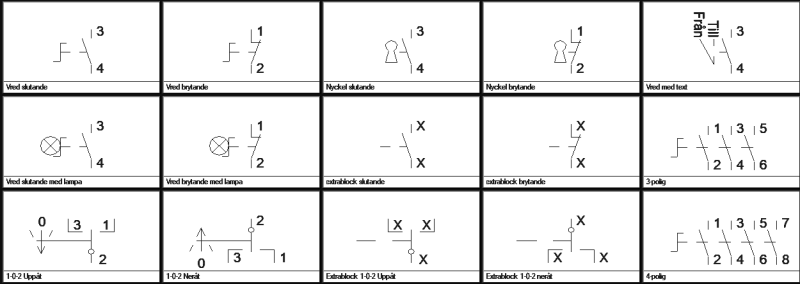
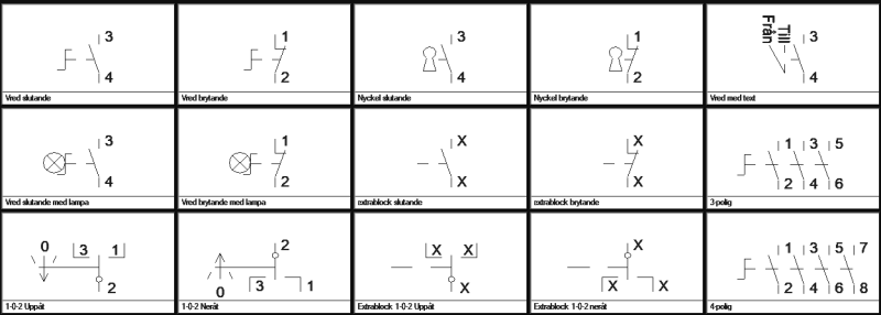
I use a program called EasyEl when I need to do an occasional non-Electronic drawing. It has the following symbols:

EasyEl_str%C3%B6mst%C3%A4llare_1_duod69.png


EasyEl_str%C3%B6mst%C3%A4llare_2_y1u71l.png


A Cardinal rule is that ALL symbols are drawn in their non-actuated position. Relays without coil voltage, switches in their neutral position and limit switches non-actuated.

If that rule is followed, much of the confusion illustrated in this thread just goes away.
Sorry for the Swedish text. I could have switched to English, but haven't the guts to do so. That COULD affect my drawings that I do not want to be changed. Not the least.

Gunnar Englund
--------------------------------------
Half full - Half empty? I don't mind. It's what in it that counts.
 
Hi,

I am proud that this post has reached 47 replies. It is clear that everyone has a different opinion based on their experience and based on their needs (because, in conclusion, IEC is NOT clear in how to draw switches), but I think that the debate that was developed on such a simple subject is very interesting

Thank you everyone!

JBC
.......
"The more I read, the more I acquire, the more certain I am that I know nothing"
 
Yes! Proof the IEC symbols are idiotic.

All of Gunnar's depictions fail to show something even close to the simple switch you needed.

And he gets a star for it!
316wvna.gif


Keith Cress
kcress -
 
Hi keith

I felt the LPS was earned because of the suggested software brand he utilized, the symbols are easily understood and most of all
due to his mention of the cardinal rule which adds clarity to the diagrams. The rule alone is significant!

As always no disrespect to you and Bill, your advice is really great and food for thought for sure. I did notice that there are
plenty of other comments on this post worthy of a LPS as well, someone is being a little stingy with the left click button on mouse.

[smile]

Chuck
 
flexoprinting said:
However, somehow not only do contact blocks get mixed up but also the switch blocks as well. A few weeks ago I found
two N/O, (auto/manual) blocks with a switch block that engaged both at the same time because the cam action was so different.
I've been there too and got the tee-shirt.
That is the condition that I am trying to describe
That is the condition that I am trying to avoid.

I have generally been able to follow a control drawing.
I agree that in some circuits, it is not feasible to show all contact positions in all operator positions.
Drum switches and drum sequencers are two examples that come readily to mind.
In such cases my preference is that the connections be described in some type of truth table.
Rather than showing the contact as two small circles with a bar in either the normally open or in the normally closed position, The two small circles are shown without any connecting bar. The technician is not misled by a contact shown in the wrong position. He sees and checks the truth table.
I have read drawings that were easy to read and I have read drawings that were confusing and misleading, but I was able to eventually understand them.

My first supervisory position was in a large automated mill.
The stated cost per minute of down time was equal to a days pay for a foreman. When the mill went down we were under extreme pressure to get it running again.
Fortunately our drawings were excellent.

I have tried to suggest the most understandable and least confusing method of depicting the switch from the point of view of the people who may be trying to repair a stopped machine under the pressure of lost production. Time is often of the essence and any confusion with a drawing is too much confusion.
Did we bother to complain about the confusing diagrams? No. The equipment had to be fixed within minutes or at the most hours. Once the equipment was back in operation we exchanged a few snide remarks about the designers and moved on.

Not one customer has complained.
Why am I not surprised. It's not worth the time.

Actually I did ask for some information once and when I got the information I did complain. It turned out that the drawings being shipped with the gen-sets were not the same as the drawings being sent to the engineering sales office. Once we got that sorted out, the sales engineer and myself became good long distance friends and worked well together for quite a few years.

Lionel, I have a lot of respect for you and do not often find myself in disagreement with you.
I think that we must be on different pages.
I have no issue with a drawing which shows a contact block with no contact shown and the action described in an accompanying truth table.
I do get a little reactionary when a drawing clearly shows a contact as closed when the truth table shows the contact open.


Bill
--------------------
"Why not the best?"
Jimmy Carter
 
Hi Bill,

Although I hadn't really thought of it that way before, the old BS symbol effectively is a truth table within the symbol itself. Thanks for making that connection.

I think the disagreement over NC or NO contacts and the bare contact block v's the assembled switch loses its way somewhat once we're talking about switches with more than two positions. For two-position switches I find myself agreeing with you in terms of how to depict them but I completely understand Lionel's option too and in almost every other situation I would agree with him.
 

LionelHutz said:
At work we have provided customers with 100's of drawings that DID NOT show the contact opened or closed as they'd be in one of the switch positions. Not one customer has complained. So, I don't find much merit in any argument that the switch drawing has to show the contacts the way they are when the handle is in one of its positions. The table or lines and X's showing when the contacts are closed make it quite clear in what position the contacts are closed.

I can't imagin having little truth tables all over a diagram instead of switch displays, truth tables take up more room
which means more pages for a given machine increasing the size of the book creating a very bust schematic visualy.

In a production atmosphere simplicity and clarity are key. Possibly it's all perspective depending on what one is comfortable with.

Chuck
 
I have found that most drawings done by consulting firms are very clear and unambiguous.
If a drawing is confusing, that leads to mistakes by installers and extra costs to repair.
Extra costs cause push back and change.

Drawings supplied by OEMs fall into two classes.
1. Excellent. Clear and easily understandable.
2. Not quite so easy to read. This is not perceived as a problem because all the OM people are familiar with the product and know what the drawing really means even though it may be somewhat ambiguous or misleading.
Eventually the field people figure it out.
Does anyone complain?
Honestly, if you're an electrician or technician and can't use the info marked on the drawing that tells you in what switch positions the contacts are closed or open when troubleshooting the circuit then you really should be looking for a new job.
Honestly.
With this attitude, I can't see even a valid comment being passed on and evaluated.
Is this what hubris looks like?

Bill
--------------------
"Why not the best?"
Jimmy Carter
 
May I, perhaps, remind you that the OP asked about IEC symbols?

The first example in the first row (from EasyEl) shows the closing contacts and the fourth example in the second row is an axtension (the opening contacts) that one just drops in place. The system then "fills in the X) so that a correct symbol with the right numbering is created.

To do the same, but creating an ON-0-ON symbol, you just use the first symbol in the last row and add the extension (third in the same row) to get what later appeared in the thread (the Auto-Off-Manual etc switch).

Gunnar Englund
--------------------------------------
Half full - Half empty? I don't mind. It's what in it that counts.
 
I agree completely Gunnar.
The issue as I understand it:
The selector switch, due to the shape of the operating cam, uses two normally open contact blocks.
Because of this, some are advocating showing the drawing with two normally open contacts.
The switch, as assembled and installed, has one set of open contacts and one set of closed contacts as shown by your suggestion.
Some seem to be suggesting showing both contacts as normally open.
Maybe I missed something.

Bill
--------------------
"Why not the best?"
Jimmy Carter
 
Schematics.. Of the machines I repair I get to see a schematic in about one out of 20 cases because they're either missing or the useless companies that "provided schematics" ALWAYS leave out the details someone needs to actually repair the machine, leaving only the unimportant stuff like 8 motors and their leads and contactors (like anyone needs that!).
vpc46w.gif


Keith Cress
kcress -
 
Bill, we used to draw schematics with the contacts shown in one of the switch positions and fielded plenty of questions about it being drawn that way and how to interpret the schematic. Hell, we used to draw 2-position switches with the contacts shown in one position and the "handle" shown only going to the text for that position. That's would satisfy exactly what you are advocating yet it caused a lot of confusion and we'll never do it that way again. The confusion we were seeing stopped when we quit trying to be so literal on the drawings and let the "truth table" symbols indicate when the contacts operate. We're not drawing them the way we do now because we are a stupid OEM that doesn't listen or know any better.

flexoprinting, Since we don't do IEC drawings the switch symbols we use look very much like the one Keith posted in the first response. There is no logic table taking up any extra space on a drawing since the "logic table" is right in the schematic. We do that because we didn't like the old NEMA way of having a separate drawing sheet with the operators truth tables since anyone working with that type of drawing has to flip back and forth as they troubleshoot. We've done this a long time and heard plenty about what customers don't like. Frankly, I think a multiple position switch being drawn in a schematic without a logic table is a very bad idea. The logic being shown in some clear manner is required.

The IEC symbol does not indicate any particular switch position. The switch drawings both Keith and ScottyUK posted do not indicate any particular switch position. So, why should the switch symbol show the contacts in one of the switch positions when the same symbol doesn't indicate which position the switch is in?

Fundamentally, I believe not knowing the switch position was the reason behind customers questioning the drawings we used to make. They didn't understand the switch contacts were drawn in the "off" or "hand" position on the drawing so seeing some drawn as closed and others drawn as open simply didn't make sense to them. This more or less falls back to the rule Gunner posted - draw everything neutral.
 
When attempting to draw complex switches such as ammeter and voltmeter selector switches which have four switch wafers on a common shaft with each wafer containing multiple switches and some switches being early make / late break elements, then the only sane way to approach these complex switches is a truth table approach or one of the symbols which incorporate the truth table. I can barely imagine how difficult one of these would be to decipher if it was drawn using IEC symbology.
 
Status
Not open for further replies.

Part and Inventory Search

Sponsor