Eng-Tips is the largest engineering community on the Internet

Intelligent Work Forums for Engineering Professionals

I beam or box beam for crane long travel, which is better? 11

Status
Not open for further replies.

edison123

Electrical
Oct 23, 2002
4,409
0
0
IN
For a crane long travel along a factory length, in terms of load carrying and resisting torsion while the crane moves, is a I beam of hxw with one vertical web of thickness t is better than a box beam of same hxw with two vertical webs of thickness t each as shown below? Crane supplier claims I beam is better. Both are fabricated from structural steel.


Parts-of-an-I-Beam_htcmux.jpg


box-beams-250x250_pezfzk.jpg


Muthu
 
Replies continue below

Recommended for you

Below is the CS of the LT system. Is the capping channel on the top flange recommended to prevent lateral movement?

60_MT_DG_EOT_Crane_-_Bracket_seating_arrangement_ybru4k.jpg


The vertical web stiffeners (8 mm) are spaced 750 mm apart along the length of runway and are welded to the web on both sides and both the flanges.

Muthu
 
Welding the stiffeners to both flanges is a bad idea - it will create stress concentrations and reduce the fatigue life of the beam. I would recommend welding the stiffeners only to the web and top (compression) flange and cutting the plate to such dimensions that there is sufficient space (say, 10-20mm) between the stiffener and the bottom (tension) flange.

Those stiffeners are supposed to prevent shear buckling at the supports and at other locations of high shear force relative to web resistance to shear buckling. The stiffeners will also increase the 2nd moment of area slightly, thereby improving the LTB capacity slightly.
 
I recommend reviewing your construction standard.
This calculator may provide a sanity check for several design codes, but is not a substitute for experienced engineering help. Civilbay Home > Steel > Crane Runway Beam Design - AISC LRFD 2010 and ASD 2010

Crane runways are a building component that carries almost exclusively live load, other building components see less than 50% live load.
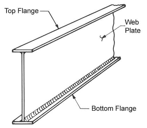
The crane will place both vertical and horizontal loads on the runway, and if the rail is not aligned with the web, a torque will be applied.

It is usually OK to weld stiffeners to the web and top flange, but not the bottom flange, and not at the web flange connection. The stiffeners need to be fitted up tight to the lower flange. The explanation is that the alternating tensile loading of the bottom flange makes any welding on the bottom flange a potential fatigue crack.

Runway beams often are stress revealed after welding.

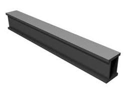
Box beam crane girders have a weight advantage on a crane, but require more welding than an I beam girder to assemble. The usual result is that once all of the parameters that create the job cost are examined, most of the time box girders will win for crane structure, and I beam will win for crane runways. Local conditions come into play sometimes that lead to other solutions like concrete crane runways in large concrete mill buildings.

Most of the discussion above I agree with, building / designing crane runways needs all of the details to work together.

Muthu The section you provide above is similar to what is often used in the US. I generally ask that the calculations be a deliverable, and do a review / comparison with the crane builders crane runway loading diagram. The design of the rail clips and pad under the rail is also important. Some rail clips have components that need to be welded to the (others require holes to be drilled) girder which is best done at the fabricators shop.
 
Thanks, centondollar.

Will check with the crane supplier if the stiffeners are welded with bottom flange or not.

Thanks for the link, FacEngrPE. Wondering if it is worth shelling out 2000 bucks for that on-line calculator. Will ask the supplier to provide the design calculations. He is a reputed supplier having supplied cranes up to 150 tons. I already visited his workshop and was impressed and hence my order on him. Design engineer is not coy about sharing his data. He said I asked too many questions. [sadeyes]


Muthu
 
I would recommend welding the stiffeners only to the web and top (compression) flange and cutting the plate to such dimensions that there is sufficient space (say, 10-20mm) between the stiffener and the bottom (tension) flange.

Forgive my ignorance of crane rail systems, but aren't the beams continuous over the columns? If they are, then at locations near the supports, the top flange is the tension flange.

Rod Smith, P.E., The artist formerly known as HotRod10
 
BridgeSmith,

Crane beams are rarely continuous over the support columns or brackets as that would involve both load multipliers and increases in the stress reversal load for fatigue analysis. Crane beams are normally simple, except in special cases.

Jim H


jim is correct.

I worked for a crane manufacturer and the only time you will se continuous beams is with light loads and low duty.

Just also be careful with the detailing of the clips/welds and the rail over the joint at the column, so that lateral loads
can still be transferred without creating continuity and a fatigue problem.
 
Just also be careful with the detailing of the clips/welds and the rail over the joint at the column, so that lateral loads can still be transferred without creating continuity...

I guess I assumed the beams would be continuous because the rails would need to be. So I learned something today; thanks guys!

Rod Smith, P.E., The artist formerly known as HotRod10
 

and triaxial stress conditions, which can initiate fatigue or brittle failure... I usually stop the stiffener at the upper edge about 1" or so below the top flange. It's easier to fit up for welding. I add stiffeners at the support bearing conditions only, not spaced along the beam unless for web stiffeneing (which I've not done), and they are welded to the bottom flange with clipped parts for the beam fillet. I wish I could get these things right the first time [pipe]

So strange to see the singularity approaching while the entire planet is rapidly turning into a hellscape. -John Coates

-Dik
 
Two more questions.

1. Should I use capped channel on the top flange as shown in above pic?

2. Since the bottom flange is the tensile member, should the web stiffeners be welded to the bottom flange and leave the top flange unwelded to reduce deflection?

Muthu
 
My answers:
[ol 1]
[li]I usually do, if I need it or require it.[/li]
[li]I usually do, and don't take the stiffener to the top flange, about 1" short[/li]
[li]If you can detail it that way, yes.[/li]
[/ol]

So strange to see the singularity approaching while the entire planet is rapidly turning into a hellscape. -John Coates

-Dik
 
That is interesting Dik.
I always assumed it would be better to stop it short of the tension flange, Gorenc recommends it here in Australia.
 

I think it still the same approach. I wasn't aware of Gorenc. Generally stiffeners are at the end of the span at the support for simple span, ie. attached to the compression flange... I don't do continuous spans except for very light and infrequent loads. The other place for stiffeners is at a cantilever, where it stops short of the tension flange, so attached to the compression flange... The stiffeners are used to provide stiffness at the supports and to maintain the cross section. [pipe]

So strange to see the singularity approaching while the entire planet is rapidly turning into a hellscape. -John Coates

-Dik
 
On bridge girders, for actual web stiffeners, without cross frames or diaphragms attached, we would fit the stiffeners to the flanges, but not weld them to either flange. For connection plates, they're fillet welded to both flanges, because of the out-of-plane fatigue stresses on the web. For bearing stiffeners at the supports, they're either finished to bear or welded using a full penetration groove weld.

As I and others have mentioned before, intermediate (i.e. not at torsional restraint points) transverse (vertical) stiffeners will not help with lateral resistance or torsion. They only resist vertical web buckling, which, with labor vs. material costs today, is more economically mitigated by increasing the web thickness.

Rod Smith, P.E., The artist formerly known as HotRod10
 
How interesting.

1) I'd've thought that a continuous beam would've reduced the loading in the beam. MDM shows that peak moments in a continuous beam are lower than individual SS spans.
2) the rail would be continuous over the supports ... being only one cap it wouldn't transfer moment.
3) why would you have the web stiffeners welded to the tension cap ? Yes, their primary job is to divide the web into discrete shear panels, a secondary job could be to divide the upper (compression) cap. What advantage in supporting the tension cap ? Maybe they help the flange bending ?

"Hoffen wir mal, dass alles gut geht !"
General Paulus, Nov 1942, outside Stalingrad after the launch of Operation Uranus.
 
Others may have different answers: [pipe]
[ol 1]
[li]I don't do continuous, even though flexurally stronger and stiffer because of fatigue reasons.[/li]
[li]I don't do rails continuous over supports, either.[/li]
[li]I generally don't use stiffeners for web stiffness... usually to transfer the reaction into the web. They also maintain the stability of the cross section.[/li]
[/ol]


So strange to see the singularity approaching while the entire planet is rapidly turning into a hellscape. -John Coates

-Dik
 
Status
Not open for further replies.
Back
Top