Continue to Site

Eng-Tips is the largest engineering community on the Internet

Intelligent Work Forums for Engineering Professionals

  • Congratulations KootK on being selected by the Eng-Tips community for having the most helpful posts in the forums last week. Way to Go!

Impact force of sliding window 1

Status
Not open for further replies.

GoncaloPT

Structural
Jun 9, 2020
24
Hi! Hope you all are doing great :)

I'm in need of some tips/help regarding some forces for the design of a structure.
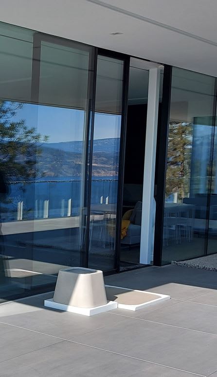
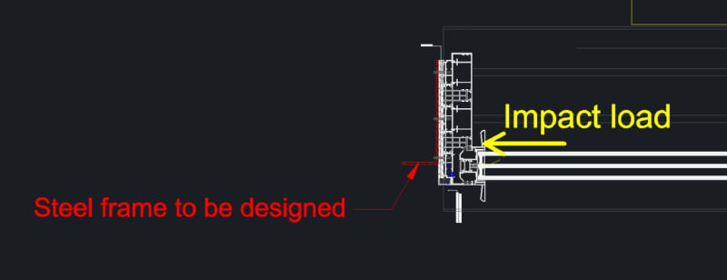
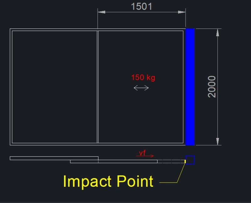
I have a sliding window that will impact on a steel square profile (represented in blue). The glazing sliding window will have a total mass around 150 kg, a impact height of around 2 meters.

Assuming a terminal velocity of 0.2 m/s (vf) what should be the impact load expected on the steel structure? Can anyone provide some guidelines on how to estimate this loads?
I understand this should also consider a collision distance and a impact duration, but i have no ideia of what are reasonable values for these.

Any input would be much appreciated :)
Capturar_x2nwgl.jpg
 
Replies continue below

Recommended for you

How can you use 0.2m/s velocity? That would take 10s to fall 2m. It's not free fall? But you say terminal velocity, which kind of means free fall is happening. You say sliding. Up/down, or horizontal? Dwg shows a horizontal 1.5m movement, not 2m. If horizontal, It will only roll 0.2m/s? What is it really? Get your facts straight.

If free fall (down)
You could estimate it by,
Force = mass x acceleration

Impact velocity
Velocity V= (2 g h)^0.5
V1 = (2 x 9,81m/sec2 x 2m height)^0.5 = 6.3m/s

Acceleration, or rather deceleration
Final velocity V2=0

Estimate a deceleration time of 0.1sec (?)
A = 6.3m/s / 0.1s
A = 63 m/s2

F = 150kg x 63 m/s2 = 9450N
Impact loads usually have a safety multiplier of 2
F impact = 2 x 9450 = approximately 19,000 N

If not free fall, enter your own impact velocity.
The real problem is estimating deceleration time. The rest is just math.


Is the window sliding sideways or vertically?
 
@XR250 it will slide sideways (horizontaly), the velocity will be imposed by the user (i'm estamating 0.2 m/s)
 
Never seen this come up as a problem before. If it was a problem, it seems that we'd be hearing about these things breaking every day. Is it a real problem?

 
Just a thought, but if the window hits a steel jamb hard enough for the steel (which I'm assuming to be HSS based on the description) to notice it's there, wouldn't the glass shatter?
 
Can you share with us the concern or the application? Is there something special going on here, different than any other sliding window? Based on the information given, this is not an issue worthy of an engineering review. If the glass can withstand the impact, certainly a steel member should be capable of resisting the same impact.
 
I have seen this problem before in the uber expensive homes. I doubt the glazing will impact the HSS. That will be furred out so it is aesthetically pleasing. The glazing will more likely have stops at the top and bottom, and those will experience load. These units are very heavy and they do not move very quickly.

glazing_nrdmtf.jpg
 
Thank you all for the attention.
I usually design the glazing solutions for windwpeeds and personal loads. But i'm being asked for the lateral loads expected for the usage of the doors.
Some window panels are considerably heavy (+900kg) and it would be good to have a rought estimation of the impact loads on the slender steel profiles. In some cases

Capturar1_dkxqcy.jpg

Capturar_xdxvtk.jpg


I found this tool online, but i'm not sure how this work:
 
They should come with bumpers, like at a rail spur dead man.

 
You can work out the impact force by equating the kinetic energy and work energy. KE = mv^2/2, W = mgd. v = vf-vo, d = distance of the drop. This assumes free-fall without friction from the tracks.
 
Seems to me that bumpers should be mandatory in these situations. The compressibility of the bumper would determine the g-load.
There have been discussions about similar topics here
thread404-74498

TTFN (ta ta for now)
I can do absolutely anything. I'm an expert! faq731-376 forum1529 Entire Forum list
 
I have dealt with industrial sliding panels that were about this heavy.
Those tracks were designed with scuff blocks in them so that about 4-6" before impact they slowed down some.
The actual last few inches were easy.
This prevented building too much momentum.
They weren't concerned about the impact load on the supports but rather damage to the seals.
Ask the manufacturer these questions.
The trouble with glass is that it is very stiff.
I don't think that strength will be the limiting factor but rather stiffness.

= = = = = = = = = = = = = = = = = = = =
P.E. Metallurgy, consulting work welcomed
 
2-m height would be more likely a sliding door vs. sliding window, which means that it's also likely to be tempered glass? That could provide some additional impact resistance

TTFN (ta ta for now)
I can do absolutely anything. I'm an expert! faq731-376 forum1529 Entire Forum list
 
In energy terms, the glass window is essentially a rigid mass. The steel jamb acts as a spring, where the spring constant (k) is derived from the stiffness and boundary conditions of the jamb member (48EI/L[sup]3[/sup], for example, assuming point load at midspan).

So setting kinetic energy of moving window = work of jamb deflecting: 0.5mV[sup]2[/sup] = 0.5kδ[sup]2[/sup]

m, V, and k are knowns, so you can solve for the jamb deflection δ. Then back-calculate to find the impact force: P[sub]max[/sub] = k*δ.

 
My apologies if I was not clear initially, the sliding windows is intended to be sliding horizontaly at a certain velocity. The goal is to calculate the impact force on the steel profile on the side.


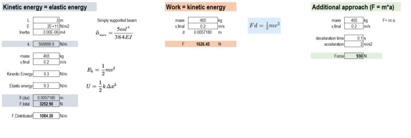
@bones206 and @1503-04 I made a comparison with both of your approachs. What do you guys think?

approach_e7t1fk.jpg


From my testing, the results tend to diverge with the increase of the beam length (it becomes less stiff). For 2 meters span, the Kinetic Energy = elastic energy approach results are equal to the ones on the Work=Kinetic energy approach, as shown on the picture below.

Capturar2_xrtsig.jpg
 
I think these approaches are too simple to be meaningful here. You're modeling this as a uniformly distributed load, which it isn't. As many people have mentioned, there are likely bumpers of some kind at discreet locations. Even if there aren't, you're not going to get that nice uniform loading. For that to happen, you'd have to deflection compatibility between the impacting mass and the frame. I'm pretty sure you will not.

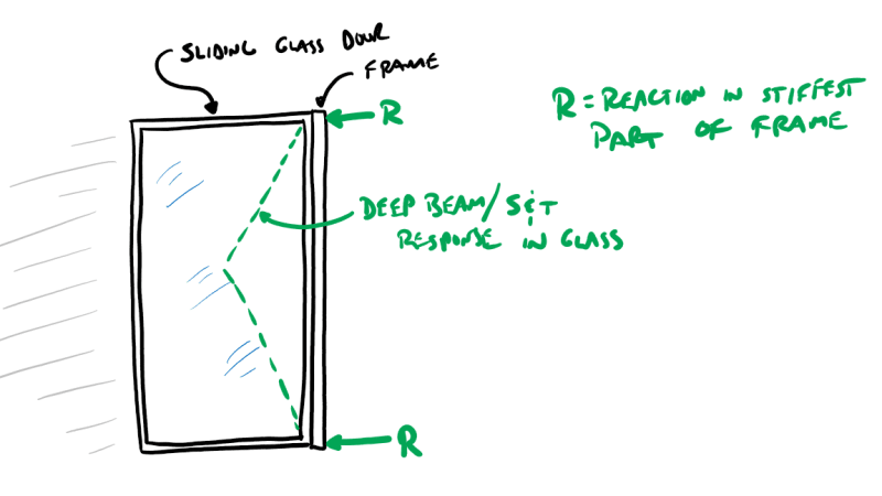
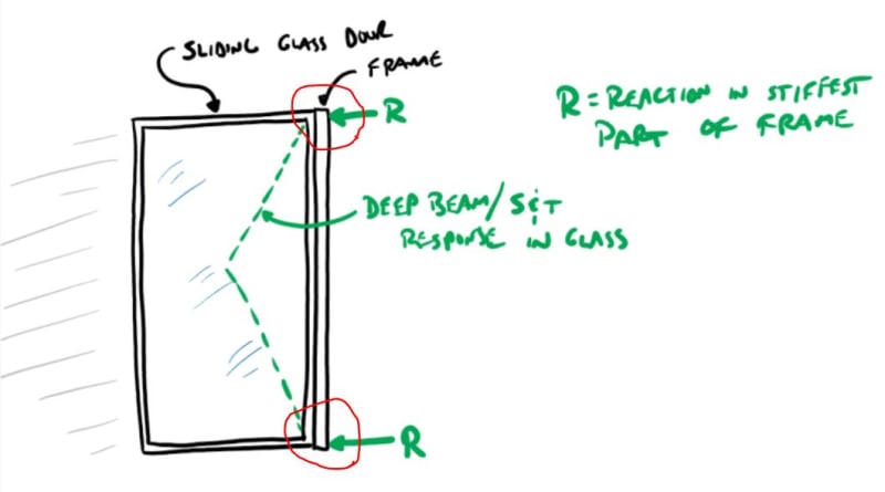
Rather than the whole thing deforming together, the door is going to act more like a deep beam. That glass isn't going to deflect to conform nicely to your frame. So instead the result will be a reaction at the stiffest parts of the frame - the top and bottom. In other words, you'll never slam the door into the frame and get a bending failure. It's going to be a shear failure - whether that's shear in the frame, tension in the connection between the jambs and the head, or shear in the connection between the jamb and the framing above.

A more accurate energy estimate would probably come from a consideration primarily of the shear deflection of the jamb (both the door frame itself and the supporting framing).

Screenshot_2022-01-25_105840_wvmez5.png
 
@phamENG you are absolutely right! I've also considered this, but I need to simplify de approach to estimate some values.
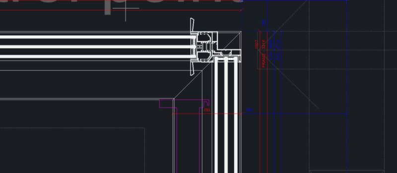
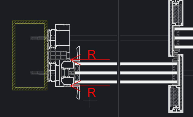
The sliding window has no bumpber, so the contact point are represetned on the picture below, on the regions you indicated on your scheme. The load is supported by the aluminum rail and and successively transferred to the steel profile.

How do you reccon this two shear forces to be calculated? Should I make a 3D model of the assembly and try to estimate the shear stiffness (model a load of 1kN and see the deflection?) of the regions indicated on your scheme?

Capturar_g91ic5.jpg


232_ke5ggk.jpg
 
That seams likes the best way to come up with a reasonable estimate in a simple way. Apply your unit load in line with the center of the top of the frame around the glass (the door itself).
 
Status
Not open for further replies.

Part and Inventory Search

Sponsor