Continue to Site

Eng-Tips is the largest engineering community on the Internet

Intelligent Work Forums for Engineering Professionals

  • Congratulations SDETERS on being selected by the Eng-Tips community for having the most helpful posts in the forums last week. Way to Go!

Indiana I-65 bridge settlement

Status
Not open for further replies.
Replies continue below

Recommended for you

oldestguy - Fishy indeed. Sounds like the DOT / Contractor are "blowing smoke" until they can figure out what to do next. As someone who grew up in a bridge-building family and had a stint as a bridge-builder myself, this whole project "stinks".

The ENR story says that inspectors have been reporting settlement of Pier 3 for 10 years. The substructure was rated "poor" in May.

I looked up the prime contractor "Walsh Construction Co.". They appear to be a large experienced firm with a long record of successful bridge projects. I wonder if they sent their amateurs to handle this project?

1. One thing my father taught me: Do your foundation (substructure) work first, at least until it is above ground / water. On this widening job, the Contractor appears to have detoured traffic, removed necessary parapets and bridge deck, roughened the surface of existing piers... then started work on the footings.

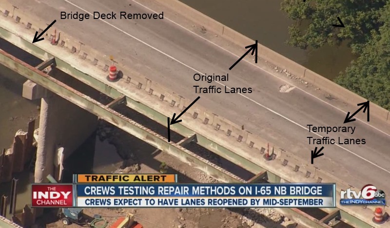
2. The bridge had settlement problems, but notice in the following photo that the traffic detour and parapet / deck removal are putting eccentric loading on the existing footings:

I-65_NB_Bridge_Deck_twwdjx.jpg


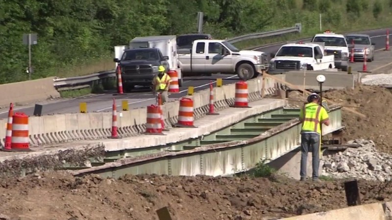
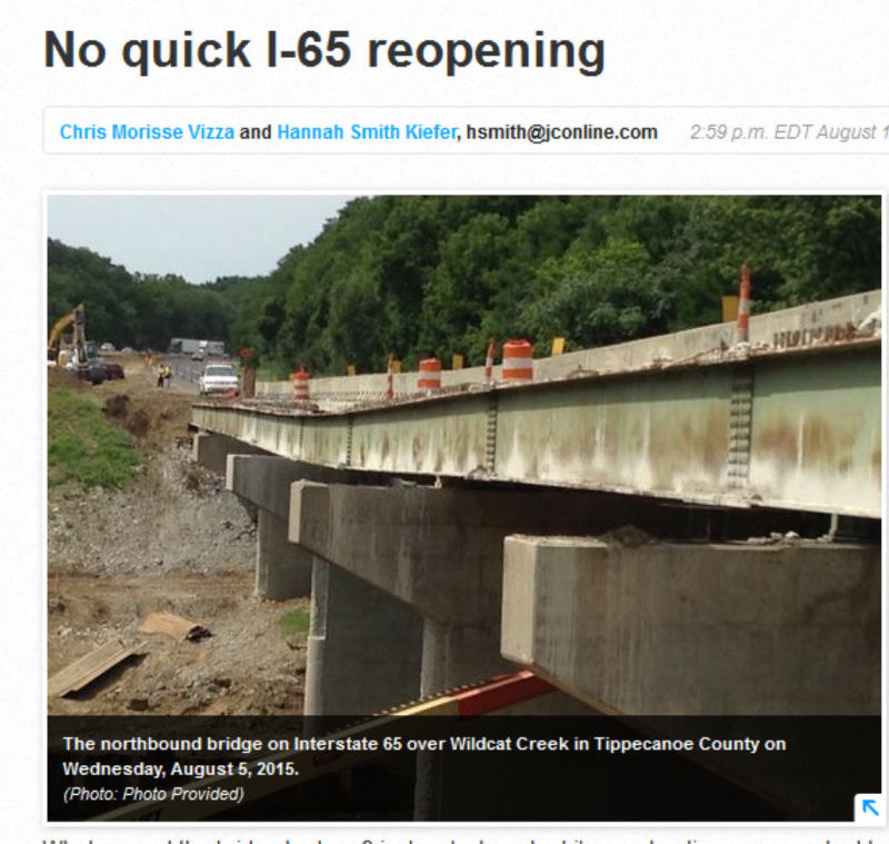
3. The eccentric loading is in the opposite direction than the "lean"... or is it? At least one girder is "off its rocker" (IMHO, Contractor too). Is the entire pier settling with the "lean" caused by a combination of pier settlement and the missing rocker? In the following photo notice that much of the deck, not just the edge appears to have settled:

I-65_NB_Bridge_Girders_tutomu.jpg


As usual, there is likely much more to this story and much of my speculation will be flat wrong. I do believe the bottom line is that this problem will not be "fixed" by mid-September. I'll come back here and "eat crow" if it is.[bat]

[idea]
[r2d2]
 
SRE...I don't see any crow in your future! I agree.

Further, the pier is incredibly thin in the direction of traffic. Odd.

Yep...mid-September is a dream.
 
oh heck. The solution is simple.

Jest pour a lot of very wet, high-slump grout mix right over the top of the drooping section of the bridge deck. The concrete evens out into the low parts of the deck = you end up with a flat upper surface. Let the concrete dry, the repaint the stripes. 8<) /sarcasm
 
A little more looking and I copy these "amazing" remarks by officials. Apparently the trouble came about in early August.

Why did the problem surface now?

The construction work, unique soil conditions and an "artesian water feature" -- a pocket of water under high pressure beneath pier #3 -- combined to create the problem, Wingfield said.

The pocket of water will move and cause a shift in the sand and compacted gravel underground if there's a change in pressure, INDOT Bridge Design Manager Jeremy Hunter added.

Pier #3, located at the center of the five-span bridge, began to move and settle on Monday, Aug. 3 after the contractor began driving pilings to widen the pier to support the additional lane, he said. The pier settled 9 inches between Wednesday night and Friday afternoon, officials said.

Could the problem have been avoided?

Prior to the start of construction, INDOT and the contractor's engineers researched bridge inspection reports to anticipate what they might run into, Wingfield said.

They knew the southwest end of pier #3 had settled into the creek channel years ago.

That didn't raise any red flags during decades of monitoring, said INDOT Director of Bridges Anne Rearick.

"It wasn't continuing to tilt," she said. "There was no noticeable change."


I-65_Aug_5_gotwup.jpg
 
If the pier was on a shallow foundation and sitting above an impervious aquifer cap as noted, then penetrating the cap would release the artesian pressure and cause settlement. Bad initial design!
 
That was my thought Ron.

Bill
--------------------
"Why not the best?"
Jimmy Carter
 
I smell a pretty massive change order. Let's see; piles or micropiles driven to China, plus you can't just do one pier, you'll have to deal with all of them, expanded footings, working under groundwater.
Walsh is a big sophisticated outfit. They're not going to eat this for goodwill.
 
Hey guys, it ain't just one bridge, it's two. Now I understand why (back in 1958) an old bridge engineer at Wisconsin DOT insisted on piles for every bridge no matter where it was located. Too bad Indiana didn't have such an engineer back then.
 
Well, I've been doing my homework on this thread. Have rounded up quite a bit of detailed technical information, such as:

1. The original 1969 bridge plans, including geotechnical information performed then. (Spread footing are pretty small.)
2. The plans for the 1988 bridge modifications. (Replace aluminum hand rail with concrete Jersey Barrier - adding some dead load).
3. The complete 2014 geotech report and recommendations.
4. The conceptual design-build plans for the current project.

Some eye openers too:

2014 Geotechnical Report - Page 7 said:
Existing plans indicate that... the interior piers are supported on spread footings with bearing elevations varying from approximately El 520 to El 526. The scour elevation for the Wildcat Creek bridges is El 515.

Scour elevation is 5 feet below the bottom of the footings!

2014 Geotechnical Report - Page 7 said:
Spread footings are not recommended for support of the interior piers of the Interstate 65 bridge additions over Wildcat Creek due to the presence of artesian ground water conditions, potential differential settlements between new and existing footings, the risk of undermining the existing spread footings, causing a “quick” condition during construction excavations to reach the existing spread footing bearing elevations and the projected scour depth.

Piles are proposed... despite the above warning about limiting the depth of construction excavation, the conceptual drawings show the bottom of the interior pier pile caps at the same elevation as the bottom of the adjacent existing interior pier footings!

This is hard to believe!

I have attached a 10 Megabyte .zip file with pertinent excerpts from the 1969 and 1988 plans plus the complete 2014 geotech report and current design-build conceptual plans.


[idea]
[r2d2]
 
Now I see why the conceptual design-build drawings shows the bottom of the Pier 3 pile cap at the same elevation as the bottom of the existing Pier 3 footing (El 520). Pages 11 and 12 of the 2014 Geotechnical report show EL 520 as the "Assumed Top of Pile Elevation (ft)".

Seems the DOT, the Contractor, and now the Geotechnical Engineer are "off their rockers".

[idea]
[r2d2]
 
Slide Rule: I think there is another party that maybe is even farther off. The consultant that drew the plans.
 
There is another factor that may not be properly handled, even if the job is done per the specs for pile driving. I have had experience with two bridges where, in time, there was gradual loss of side friction due to artesian flows alongside displacement piles. Accepting pile depth based upon driving conditions may not be sufficient in the long run. The option for H piles may be the better alternative, since they have to go much deeper. Then, now with mini-piles in the picture, what the heck will be the result of two different supports in the same piers?
 
oldestguy - I agree about the defects in the new plans. On the "Layout" page, the contour of the stream bottom looks to be a copy of the 1969 contour, which must have changed plenty since then.

There will not be much room to drill the mini-piles through the existing footing. That footing projects 9" beyond each end of the pier and just 4'9" beyond each side. The footing is only 2'6" thick. Wonder how much footing rebar will get cut when the mini-piles go thru?

The 1969 maximum footing soil pressure is shown as "3.5 tons / square foot". What are your thoughts on that figure?

[idea]
[r2d2]
 
I took a quick look at the log S5-TB-WC2. Had quite a time figuring out how to read the attachments. Didn't find a boring layout yet. However,original borings may have indicated very high blow count. I'd only use that pressure for very dense glacial till or weathered rock. Back about then maybe the borings were what Wisconsin DOT did for years, hand soundings. A rod driven by a sledge hammer. I put a change to that when I started in '58.

As to mini-piles, I'd suspect they will be alongside the narrow footings and a new pile cap would be built over them, tied into the pier somehow.
but, with the one boring showing artesian conditions all the way down to 100 feet or so, it would seem that there should be a decision by the DOT to use H piles to support the existing piers as well as any new work. Driving H piles with low head room will be interesting. Hope the welder has a lot of rods or wire electrodes.

I think someone in authority should take over this thing, sit back and think it out before proceeding. I'm wondering if the consultants really are qualified for something like this. It is a very unusual site. The deep depth artesian factor may well cause another failure otherwise. It's not in a "confined" layer.
 
Status
Not open for further replies.

Part and Inventory Search

Sponsor