Continue to Site

Eng-Tips is the largest engineering community on the Internet

Intelligent Work Forums for Engineering Professionals

  • Congratulations SDETERS on being selected by the Eng-Tips community for having the most helpful posts in the forums last week. Way to Go!

Is it valid to have a Free-State symbol here? 1

Status
Not open for further replies.

SeasonLee

Mechanical
Sep 15, 2008
917
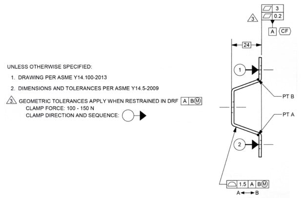
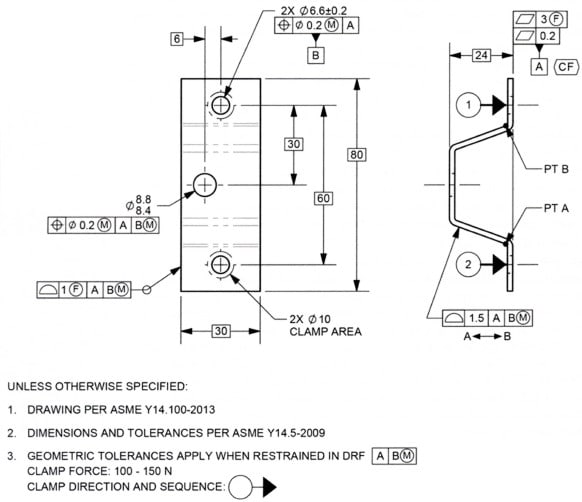
Please ref to the figure below, two questions need help:

1. Is it valid to have a Free-State symbol within the flatness FCF? Since the restraint note on the drawing will override the Free-State default condition, so I will say No, am I right?
2. What's the meaning of the 2nd segment flatness callout?
2020-06-22_114334_cd3hw0.jpg


Thank you for the help

Season
 
Replies continue below

Recommended for you

Is it valid to have a Free-State symbol within the flatness FCF? Since the restraint note on the drawing will override the Free-State default condition, so I will say No, am I right?

This is perfectly valid - the restraint note does not override the free state symbol, it is actually the other way around. The Free State symbol in this case means that the FCF and tolerances to which it is attached must be satisfied WITHOUT restraint. I see that your example is pursuant to Y14.5-2009 but this is actually the only valid use of the symbol in the new 2018 version, any references to "free state variation" have been removed.

What's the meaning of the 2nd segment flatness callout?

The top segment must be satisfied when no restraint forces have been applied to the part (ie: in the free state).

The bottom segment must be satisfied when restraint has been applied to the part, per the note.
 
chez311,
Why the example is not per 2018?
Because CF in 2009 was intended for FOS.

I know the note (#2) states 2009, but the callouts I guess are not reflecting that.
What do you think?
 
greenimi -- if I may speak for chez311, this drawing would be compliant in 2009 or 2018. As you said, the general note invokes 2009. But in 2009, there was some fuzziness about "free state variation" and the use of the F modifier; in 2018 they tightened things up to say that the F modifier's only and explicit use is to override a general restraint note. (See 2018's paragraphs 6.3.20 and 7.20.)
Chez simply meant that if the F modifier were used in another way (besides what's shown here), then it might be legal in 2009 but not in 2018.

edit: added paragraph numbers
 
J-P,

I am talking about CF (continuous feature) applied to a non-FOS in 2009
 
Doh -- my bad!
Yes, in 2009's paragraph 2.7.5 they only speak of FOS. But I recall discussion here about 2009's Figure 7-45. Though it wasn't a FOS, several of us were of the opinion that it would've been OK had they used a flatness callout on those coplanar surfaces.

John-Paul Belanger
Certified Sr. GD&T Professional
Geometric Learning Systems
 
Again, "The note “CONTINUOUS FEATURE” or continuous feature symbol is used to identify a group of two or more features of size where there is a requirement that they be treated geometrically as a single feature of size."

I am talking about CF and about this 2009 definition, not necessary about F, which was covered by chez311

 
Ok. Understood. I guess we are kind of posting in the same time.
 
Thank you JP, yes that was my intended meaning. It is of course legal in both 2009 and 2018 as shown, I just meant to say that the use in 2018 has been restricted to the application shown (overriding a restraint note).

greenimi,

As JP noted, CF is applied to a non-FOS in 2009, fig 7-45. Though the wording may suggest only its use on FOS, this figure could be used as precedent to allow its use on nonFOS in 2009. I guess some people have an issue with the use of flatness to control coplanarity, even if the intent is clear. Note this figure has been changed in 2018 to remove <CF> and add a 2X profile fig 10-46, I think this could also have been changed to still include <CF> with a single profile tolerance similar to Y14.5-2018 fig 11-23.
 
greenimi,

Please see 3.3.23 in Y14.5-2009. <CF> is not restricted to features of size. It provides a very nice (more intuitive than using profile) method of controlling coplanarity with flatness or an orientation tolerance, or a nice method to control coaxiality of cylindrical features when they're the same diameter.

Dean
 
"The figures in this Standard are intended only as illustrations to aid the user in understanding the principles and methods of dimensioning and tolerancing described in the text."

IMHO, verbiage/text trumps the figures. In a court of law the figures do not matter. Only the text.
And the text is clear: 2.7.5/2009 stated clear FOS only. (again I am talking about 2009, not 2018)

For 2018: different story.

I know you Dean have been in the committee meetings and you know the INTENT, but that is not what ended up in the actual text.
Sorry, I do not buy the argument that in 2009 CF could be applied to a non FOS.


Hi Greenimi,

Please look at 2.7.5 again. It does not have "only" anywhere. <CF> has been fine to apply to any interrupted feature since 2009, and that is backed up by the words in 3.3.23.

Many on the Y14.5 committee intended to restrict the application of <CF> to FoS only, but the words in 3.3.23 failed them :).

Dean
 
@chez311
Thanks for the comments.
One further question : If the Free-State symbol removed and a flag note added, what's the meaning of the 2nd segment flatness callout?

2020-06-22_135807_xt91bk.jpg


Season
 
Dean

Here is a copy-paste of the exact text from the 2009

2.7.5. ""The note “CONTINUOUS FEATURE” or continuous feature symbol is used to identify a group of two or more features of size where there is a requirement that they be treated geometrically as a single feature of size.""

FOS term is clearly shown in the above definition 2 times.


Greenimi,

Yes, the words in 2.7.5 define how the CF modifier works for features of size.

Since the wording of 3.3.23 is "The symbol indicates a group of two or more interrupted features as a single feature", that means CF is not restricted to only features of size. Please also notice that it is not called "Continuous feature of size" as it would or should have been if such a restriction were to be true. As you say, the words rule and the words in 3.3.23 clearly allow CF to be applied to any interrupted feature.

Dean
 
Dean,

Here is 2018 text

"3.10 CONTINUOUS FEATURE continuous feature: two or more interrupted features designated with a “CF” symbol, indicating they are to be considered as a single feature. See Figure 11-23.
3.11 CONTINUOUS FEATURE OF SIZE continuous feature of size: two or more regular features of size or an interrupted regular feature of size that is designated with a “CF” symbol, indicating they are to be considered as a single regular feature of size. See Figure 5-11."


Again, going back to 2009 I am still not convinced that you are correct...Yes, even you came from Y14.5 committee meetings and you are committee member.
Sorry, to be stubborn…..You are an authority in this area, but...….


Greenimi,

Well, we all have the right to be stubborn, and the right to our opinions :). I stubbornly (edit) think the opinion you're stubbornly sticking to is that the words in 3.3.23 don't matter :).

Dean
 
Season,

I would say that the result for the flatness tolerance is the same, just instead of a general note which applies UOS you now have a note for a restrained condition that only applies when the flag is attached to a tolerance specification/FCF as in 0.2mm flatness tolerance. Now the (F) free state symbol is not necessary to add to the 3mm flatness tolerance to indicate it applies in the free state without restraint.

The big difference lies in the rest of the tolerances. Say the 1.5 profile tolerance, in your (22 Jun 20 19:05) figure it would apply in the restrained condition since we would assume the note applies UOS. In your (22 Jun 20 20:59) figure it would apply in the free state.
 
Dean,

The words in 3.3.23/ 2009 are related with the symbology only and not the continuous feature CF definition (and I would add applicability).
At least this is the way I, personally, read the way the standard is written and structured (chapters, paragraphs and "verses")


3.3.23 Continuous Feature Symbol This symbol indicates a group of two or more interrupted features as a single feature. See Figs. 2-8 through 2-10 and 3-11 and para. 2.7.5.
 
chez311 said:
I would say that the result for the flatness tolerance is the same
chez311 said:
Now the (F) free state symbol is not necessary to add to the 3mm flatness tolerance to indicate it applies in the free state without restraint.

I'm confused here, would you please talk it in more details.
Thanks again

Season
 
Status
Not open for further replies.

Part and Inventory Search

Sponsor