Continue to Site

Eng-Tips is the largest engineering community on the Internet

Intelligent Work Forums for Engineering Professionals

  • Congratulations KootK on being selected by the Eng-Tips community for having the most helpful posts in the forums last week. Way to Go!

Localized Datums in a print with patterns 1

Status
Not open for further replies.

rsm7400

Industrial
Mar 6, 2012
52
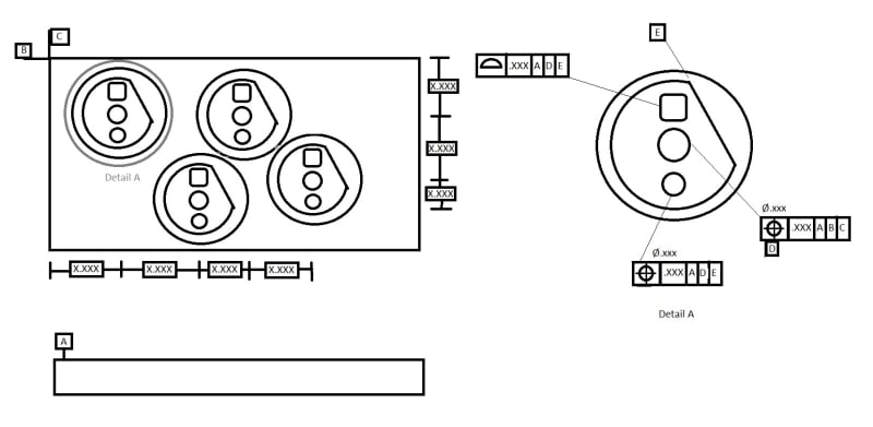
I have large rectangular part with several identical patterns in different locations with datums called out to the main part and some features to the localized pattern. See the mockup sketch attached, these are not my actual features but mimic what I am seeing.

Yes I know I didnt draw all the basics, and i didnt draw all the depths, etc. Its more how do I call out the following:
In Detail A you can see the center hole is called out as datum D, location controlled by A|B|C
The other 2 features in the pattern call out profile or position to A|D|E
This pattern is repeated multiple times.

In the next pattern location the profile will be called out to that respective center bore, and clocking flat.
Can I call the detail A out multiple times (4x in this example) and will that imply to use the localized datums? Or do I have to do a detail circle for each of the pattern locations?

Hopefully what I am asking makes sense?
GDT_Example_ms8qxb.jpg


________________________________
Ryan M
Quality Engineer
3d Printer Hobbyist
 
Replies continue below

Recommended for you

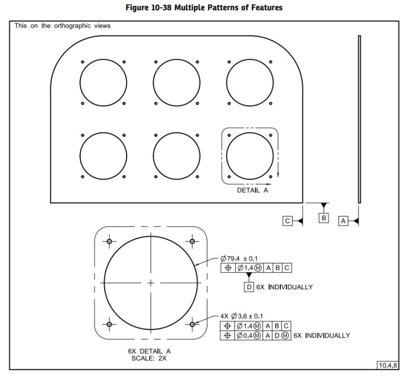
The repeated datum feature is indicated with a note to the side like "4X INDIVIDUALLY" and each feature control frame that uses the repeated datum feature reference is indicated with a note to the side like "4X INDIVIDUALLY" where the number is replaced with the number of features you have.

 
Figure 10-38 from 2018 version(or figure 7-37 from 2009 edition) is a good reference on your case.

2022-12-21_hqk6yd.jpg


Season
 
That example is an interesting example and would be a great example if the committee added an explanation of why there are two feature control frames on the set of smaller holes. The upper of the two feature control frames (FCFs) is not required or, at least, no explanation of the requirement is given, though without it, the lower FCF would require adding a rotation control reference. As it is the upper FCF for those holes require inspectors to determine the hole locations to three datums but it only retains value with respect to one of them, a needless duplication of effort.

Moreover there is the chance to pass the upper FCF requirement and fail the lower FCF requirement - again, without adding value as failing the lower one is sufficient, making the upper one again a needless duplication of effort.

It also raises the question of why it is necessary to include "6X " on the datum feature symbol and the related feature control frame and not have the total number "6X " on the large hole and "24X " on the smaller holes, since the detail already carries "6X " as a prefix.

They even note that "When a detail view includes a notation of the number of occurrences of that detail view, then the “6X” on the “INDIVIDUALLY” notation may be omitted." and then it carries on as if they had not just mentioned that and gone inconsistently to that figure.
 
3DDave,

I'm not sure that having two FCF's for the smaller holes is a duplication of effort. The upper FCF controls the clocking of the holes relatively loosely and then the lower FCF refines the centering relatively tightly. The inspection would need to include two different alignments, and there is a chance that the holes would pass one requirement and fail the other. I don't see a fundamental problem with any of that, if the purpose was to provide the loosest tolerances required to satisfy the function of the holes. I suppose that the value added depends on the savings from the looser tolerances versus the cost of the additional drawing complexity and inspection setups.

Evan Janeshewski

Axymetrix Quality Engineering Inc.
 
The lower only needs one clocking datum feature to be added. It doesn't require a complete separate setup, inspection, and reporting.

It adds little and costs a great deal for it. If it was to make the tolerance looser then it should be explained that this is the need and to show exactly how that effect happens - but it's instead a "this is exactly how this exact task is done - ask no questions, there won't be answers given."

The large holes locate the instrument in the panel; that amount might have been a position of dia 0.500 inch. Then the small holes need to follow the big holes around so the screws can go through, but they also need to precisely clock the instrument so the displays are lined up from instrument to instrument. This depiction fails to do that and can prevent the instrument from being turned to make that alignment.
 
Awesome! Thanks for the inputs. I knew there had to be a way my brain just couldn't figure it out yesterday afternoon. I already have over a dozen edits for the new engineer who drafted the real print. Tons of missing information and then over constraints in many locations. [upsidedown]

________________________________
Ryan M
Quality Engineer
3d Printer Hobbyist
 
Status
Not open for further replies.

Part and Inventory Search

Sponsor