Continue to Site

Eng-Tips is the largest engineering community on the Internet

Intelligent Work Forums for Engineering Professionals

  • Congratulations KootK on being selected by the Eng-Tips community for having the most helpful posts in the forums last week. Way to Go!

Locating a spotface 3

Status
Not open for further replies.

Burunduk

Mechanical
May 2, 2019
2,339
What is your way of specifying and controlling the location of a shallow spotface for which the depth is specified and is smaller than the fillet radius?

The standard is Y14.5-2009.

Thank you
 
Replies continue below

Recommended for you

Burunduk,

My way to specifying a spotface is to apply the controls that I need to make the part work. If a spotface retains another accurate part, I will specify a diameter tolerance, and a positional tolerance. If the outline is not critical, and/or I require a reliable keep[‑]out, I will apply a profile tolerance to the diameter.

GD&T is not a procedure. It is a language.

--
JHG
 
I wanted to say something smart, but then I was confused of my feet:
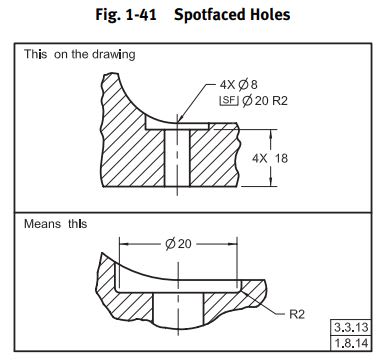
Is spotface diameter Feature of Size?

Capture_okag4v.jpg


"For every expert there is an equal and opposite expert"
Arthur C. Clarke Profiles of the future
 
CheckerHater,

In my first example, it would be. It all depends on requirements.

Do you specify the depth of the spotface from the top, or do you specify the thickness from the bottom? Again, it depends on requirements.

--
JHG
 
What I am saying, by definition, diameter is applied to flat feature without "opposing points".
If you apply diameter to the sidewalls, it's not a spotface, it's counterbore.

"For every expert there is an equal and opposite expert"
Arthur C. Clarke Profiles of the future

 
Maybe I'm overthinking it, but I think the question implies there is no diameter involved from which to dimension a FOS.

CH - I do not believe the 20 dia as shown in your figure is a FOS. I would not attach a position FCF to it.

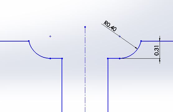
which the depth is specified and is smaller than the fillet radius

Pardon the rough sketch, I'm imagining something like this. Seems to me the simplest solution is to use profile.

cbore_bykjd5.jpg
 
chez311,

If I apply a [±][ ]tolerance to the face and locate it with a positional tolerance, it is a feature of size (FOS). Why would I do this?

--
JHG
 
drawoh,

I too am wondering why you would do that. I was under the impression (perhaps incorrectly) that OP was concerned about the radial location (perpendicular to the associated hole axis) of the spotface and NOT the longitudinal location (parallel to the associated hole axis) aka depth.

Or are you contending that the 20 dia in the "means this" portion of CH's figure 1-41 is a FOS?
 
chez311,

A spotface is a feature on your part. You have a set of requirements for it. You apply dimensions and tolerances to meet that requirement. There are multiple ways to specify it as per ASME Y14.5[‑]2009. You pick the one that works. This is the point of my original response.

I did not consider the radius at the bottom as per CheckerHater. Why would I do this? Do I care about the flat, or about the perpendicular edges? My drawings normally have a note specifying maximum radii (unless otherwise specified). If something matters, it will affect my dimensioning scheme. His section views definitely are a good idea.

--
JHG
 
chez311 said:
I was under the impression (perhaps incorrectly) that OP was concerned about the radial location (perpendicular to the associated hole axis) of the spotface and NOT the longitudinal location (parallel to the associated hole axis) aka depth.

The impression you got is correct. The "perpendicular to the associated hole axis" direction is the one I'm interested in.
Your sketch is a good representation of the geometry in question: the core of the problem is that there's no cylindrical portion to consider a positional tolerance for (and as CH noted, a spotface is anyway dimensioned by the diameter of the flat area, such as the 20 from the Y14.5 figure posted, which is definitely a feature without size).

Often with spotfaces, the depth can be even smaller than in your sketch - a tenth or a few hundredths of a mm. And that is when I think a profile of a surface requirement might become difficult to evaluate. Wouldn't it? But one would still need to control the size and location of that fillet to clear whatever sits on the flat area of the spotface.

Last time I did something like that I applied a solution that I believe many would find questionable: specified a directly toleranced diameter on the edge where the fillet of the spotface connects to the surrounding surface (not the internal flat area as shown in Y14.5) made it so that the "MMC" size of it was larger than the largest part that is mated to the surface by more than twice the fillet radius, and applied position at MMC. But technically, the above-mentioned edge diameter I associated the position to is not what I consider as a FOS either (the unrelated AME is unclear), so I don't like the "illegality" aspect of it. Thoughts?
 
drawoh, I believe that the reason why the standard specifies that spotfaces are dimensioned by the diameter of the flat area is that often the cylindrical portion is very small, partial, or non-existent. CH's figure is from Y14.5.
 
Burunduk,

The only reason to control the flat portion of a spotface is that you care about the flat portion of the spotface.

In ASME Y14.5[‑]2009, Fig[ ]1[‑]41 is showing a the notation to specify a flat portion of the spotface, and the radius around the bottom. The notation is obscure enough that your machine shop is likely to miss it. To do the spotface in Fig[ ]1[‑]41, a machine shop would have to grind the 2mm[ ]radius onto a [⌀]24 end mill, and recognise that they need a [⌀]24[ ]cutter.

Why would I apply an accurate diameter to the flat part of the spotface? If something is being located by the spotface, I would specify an accurate hole diameter, specify a positional tolerance, and make sure the located boss or part is chamfered. If the clearance is not accurate, I would make the OD several millimetres larger than the boss or washer, making the radius not critical.

In ASME Y14.5[‑]2018, this is Fig[ ]4[‑]39. I cannot find the notation in ASME Y14.5M[‑]1994.

--
JHG
 
drawoh,
In the '94 standard, it is Fig 1-40. The diameter 20 pertains to the flat area, there too. The corresponding subparagraph is 1.8.13 that starts by saying: "The diameter of the spotfaced area is specified." The "area" mentioned is the flat portion of the spotface.

In the '09 standard the subparagraph is 1.8.14 from which a similar conclusion can be drawn.

The whole point of spotfacing is removing a thin layer of material just enough to prepare a portion of a surface to be flat enough for a mating part to rest on with enough planar contact. It is often intended not to change the height of the surface considerably, that's why the standard allows not to specify the depth or the thickness of the remaining material as the 09' standard specifies: "If no depth or remaining thickness of material is specified, the spotface is the minimum depth necessary to clean up the surface
to the specified diameter."

So my point is that the OD may not even be there (see chez311's sketch). The flat portion is always the main thing we care about. It doesn't mean that the diameter of the flat area needs to be accurate, but it needs to be controlled somehow to be large enough and located properly to keep away the mating part from the fillet surrounding the flat portion and the surrounding less accurate surface.
 
Burunduk,

ASME Y14.5M[‑]1994 Fig[ ]1[‑]40 specifies the outside diameter and section thickness of a spotface. The radius and the flat diameter are not controlled.

The whole point of a spotface is that I want a spotface for some reason. That reason will dictate my dimensioning and tolerancing scheme.

If I need the spotface to seat a screw and washer, the position of the hole is critical, the thickness is somewhat critical, and the OD can be oversized and sloppy.

--
JHG
 
drawoh,
In the '94 version, it was somewhat vague which diameter is intended to be of the specified size because the symbol that was used for a spotface was the same as for a counterbore. However measuring the OD was never practical because, again, the OD might not even be on the part, so it doesn't help that the drawing permits it to be "sloppy". The function of the spotface is often just to clean up the surface.

In the 2009 standard, to clarify the ambiguity, a new symbol was added to specify a spotface diameter. This new symbol precedes the twenty mm diameter in fig. 1-41 (as posted above by CheckerHater), and the "means this" portion indicates that the diameter associated with the symbol pertains to the flat area only, and not to the OD. It definitely doesn't define the size of a feature of size, so this diameter can't be associated with a position tolerance (because it's impossible to derive a center axis from it), hence my question in this thread.

Maybe I should clarify my question: How would you specify the location (in the direction perpendicular to the hole axis) of a spotface if, for example, you would care about it being somewhat centered to the hole, but the depth of it needs to be such as no OD is available?
Profile was suggested, but for a very small piece of a fillet available (imagine the depth was 0.1 in chez311's sketch while the fillet radius was still 0.4) it may be difficult to evaluate.
 
I know I said profile in my initial response, but I was shooting for "most unambiguous" (and was perhaps thinking of the cases where the spotface is not so shallow) - if I'm to play devil's advocate (and what drawoh has sort of hinted at) the easiest and likely most common method is to simply apply a diameter which is sufficiently oversized so that any reasonable amount of manufacturing variation will still produce a spotface which is of acceptable size/position relative to the associated hole. The diameter can have a relatively tight diameter tolerance so that it would have to be produced with significant location error to cause an issue. This is probably "good enough" for 90% of applications. Understanding that its meaning is at best ambiguous per Y14.5, if you really want to kick the can down the road you could even apply a position tolerance to the circular section, and leave it to manufacturing to decide how to interpret that - at least you've communicated your desire that the spotface should be accurate within a certain margin.

For more critical applications where sufficient oversizing of the spotface is not possible, or manufacturing cannot be relied on to produce this feature "good enough" it might be a good idea to sink it a sufficient depth to produce a counterbore with walls from which an axis can be extracted and a position tolerance applied.

If we're to take it a step further, keeping a spotface instead of a counterbore, and taking it into what is probably overkill territory for most applications - lets consider what our functional objectives really are. We don't actually care about anything on the spotface besides the flat portion - this might be applied on a rough and drafted cast surface where we want to have a completely machined circular area of some minimum size around the associated hole. Whatever the "position" variation of the outer edge (if we're to conveniently gloss over the ambiguities of position of a single circular segment) doesn't really matter. I've never seen anything like this specified, but like I said - overkill, one could set up a limited area of basic diameter, then apply a profile tolerance and note to the effect of "LIMITED AREA MUST ONLY CONTAIN MACHINED SPOTFACE - NO VOIDS, CAST SURFACE, INTERRUPTIONS OR DRAFT ALLOWED. LIMITED AREA MAY NOT BE VIOLATED - SURFACE MUST BE COMPLETELY WITHIN THE DESIGNATED AREA". I'm sure someone can come up with a better note, but I'm just throwing something out there.
 
chez311, thank you.
"its meaning at best ambiguous per Y14.5".
I was suspecting so.
The standard provides the means to dimension a spotface but not to tolerance it.

If I am to specify a relatively tight diameter tolerance to compensate for the lack of location control as you suggested (and I agree with the logic), there should be a meaningful way to interpret that tolerance. The diameter dimension associated with the spotface symbol pertains to a nonsize feature per figure 1-41 in the '09 version and figure 4-39 in the '18 version so again there is ambiguity. If the concept is covered by the standard and there is even a dedicated symbol for it they should at least suggest a method of meaningful tolerancing.

I like the last "overkill" suggestion with the basic diameter however we sometimes do care of where the external edge ends up being. As far as I'm concerned the concept of a spotface can be widened to any very shallow pocket, not necessarily only round ones, where the minimum possible height difference between the spotfaced area and the less accurate surface around it is desired. The contour of spotfaced feature may follow the shape of an interface feature of component that uses the flat area as a clamping surface in an assembly (not necessarily a round head of a bolt). The spotface may be machined inside a pocket and the oversizing of its surface may be limited by other features that need not be interrupted by the operation. In this situation I resort to methods I don't like such as locating the external edges of the spotface by directly toleranced dimensions from the surrounding features. As much as I dislike using +/- for location, manufacturing and inspection would dislike profile on the thin strip of a partial fillet that limits the soptface much more. Ever encountered similar situations?
 
Hi Burunduk,

How short can a cylindrical feature of size be? Can it have an axial length of 0.05mm? Maybe even shorter? Maybe it needs an axial length equal to its diameter?? What if a circle is printed in some zero thickness way onto a piece of mylar or onto a piece of glass? Is that 2D circle not a feature of size? The only orientation of that circle, or for that matter of any cylindrical hole cut through relatively thin material, will come from the planar surface it is printed on or cut through. That assumption is made every day when inspecting sheetmetal parts.

Can a 2D circular feature with no axial length constrain a circular mating envelope? If that circular mating envelope is lying on the same planar surface that the circular feature is printed onto, then I think the answer is yes.

If that circular feature is all I care to control why can't I put a directly toleranced diameter and a position tolerance on it? Clearly the viewing orientation to measure the circular feature is normal to the planar surface the circular feature is printed on. It might be nice if Y14.5 was written in a more general way that more clearly supports this, but what makes this an unacceptable extension of principles?

When we put a position tolerance on a hole punched in a sheetmetal part do we say that the position controls the location and orientation of the hole, or just the location? The only practical answer is that the position controls location only. For the measurement of that feature we will orient to the surface the hole is punch through, just as we must orient to the surface a 2D circular feature is printed on, or machined into.

If you specify a directly toleranced diameter of the planar surface a the bottom of the spotface, and include a position tolerance with a tolerance zone diameter of whatever you need, relative to any datum reference frame you deem appropriate where does that fail?

We should be trying to maximize profit, or at least ensure adequate quality at the lowest possible cost, rather than rigidly following a standard, so I would recommend this approach for a spotface if a location tolerance is needed. The wording in Y14.5 should support this, but no need to leave the location untoleranced just because the standard hasn't been written in that way yet. If discomfort or refusal is encountered then a short flag note to explain the already clear meaning should make things proper enough.

Dean
 
Thank you, Dean. I've been hesitant on applying position tolerance on features for which the unrelated actual mating envelope is not clearly defined - such as where we need to assume a specific orientation as you described, which makes the AME not completely "unrelated" in a sense (would you disagree?). But I suppose that sometimes it is required to make an exception.
 
Hi Burunduk,

Yes, I completely agree with your assessment that the U part of UAME gets sketchy for features that are incapable of orienting the mating envelope due to insufficient length/depth. This is dealt with every time a sheet metal part is measured and really no different if the diameter of the planar spotface surface must be measured, along with its radial location.

Y14.5 needs some words to describe and support these situations. The part designer is in the best position to decide when the mating envelope should be oriented normal to the surface the feature is cut into instead of the normal orientation constraint from the feature itself. This is very similar to when a decision must be made about whether two opposed, parallel, but not fully overlapping planar surfaces can be treated as a feature of size or not. Surely 99% overlap is sufficient and 1% overlap is not. Where to draw the line for how much overlap is sufficient and how to make that decision for a given feature is up to those who designed the part or assembly. The standard cannot make that decision for the designer but for these two cases the standard needs words to describe and support the decisions.

Dean
 
Status
Not open for further replies.

Part and Inventory Search

Sponsor