Eng-Tips is the largest engineering community on the Internet

Intelligent Work Forums for Engineering Professionals

Locating a spotface 3

Status
Not open for further replies.

Burunduk

Mechanical
May 2, 2019
2,335
0
0
IL
What is your way of specifying and controlling the location of a shallow spotface for which the depth is specified and is smaller than the fillet radius?

The standard is Y14.5-2009.

Thank you
 
Replies continue below

Recommended for you

3DDave said:
Since a tapered feature is not a feature of size, by definition, there can be no MMC/LMC allowed. It has nothing to do with different values (local size) along the feature

It has to do. Because a circular or parallel lines 2D element at a specified location can be of defined unique size limits. Full features that are tapered have no unique size that can describe the feature at its full length.
 
Dean,

I don't want to drag this discussion further than need to be, but see below a print screen from a webinar late prof Don Day - former chair of Y14.8- had on casting, forgings and molded parts
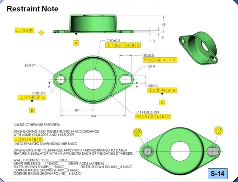
In the example below, he used -DFT and position modified at MMC for Ø114 ± 0.3 feature . Do you think that is a mistake?
Very well could be, I am not disputting it, but trying to understand all perspectives.
Now if <FF> is added, then I do understand that the position is to be applied to the full feature,correct, but don't you think that as currently shown, the position is already applied to the full feature too? Otherwise stated, would not change the meaning of the drawing regardless if <FF> is added or not.
In Don's example, I think the common understanding is that the entire feature is to be controlled and not only the 2D circular element at the mold line.
Or in other words, <FF> modifier is not needed at all.

If <FF> is added, would just make it "illegal" to use MMC in the position? Just does not sound right, IMHO.

What do you think? Any input from the committee's perspective is grealy appreciated.


DD_-_Copy_efcgje.jpg
 
Burunduk,

In slower words ... the variation in section is not a necessary condition to exclusion from MMC/LMC because MMC/LMC is already excluded by an explicit definition for applicability of MMC and LMC.

Are you arguing for an extension to an existing principle?

If it's only that there is a constancy to some dimension then that would conflict with the definition excluding a helical feature of square or hexagonal section. They do not taper.
 
3DDave said:
n slower words ... the variation in section is not a necessary condition to exclusion from MMC/LMC because MMC/LMC is already excluded by an explicit definition for applicability of MMC and LMC.

Are you arguing for an extension to an existing principle?

I think that the principle was already extended when it was decided to standardize the application of position tolerance to tapered features.

 
Hi Kedu,

I knew Don well. I wish he was still with us so I could discuss that figure with him. I think it is wrong, but Y14.8 almost sort of supports it by including tolerances at MMC and LMC in the figures. I say almost sort of because Y14.8 doesn't explain how to deal with tolerances that apply to mold lines modified at MMC or LMC.

It's interesting what goes unnoticed until someone brings up a good question. The mold line concept has some ambiguity, since the extents or ends of a feature are not defined well in any standard. I would never recommend modifying a tolerance at MMC or LMC if +DFT or -DFT or the other way "Draft adds material" or "Draft reduces material" are applied. I say that because I don't think any evaluation with those modifiers can address functional requirements in any way that can be considered effective.

I will recommend that we drop the entire practice and fall back to controlling only the surface of a drafted feature and not anything to do with the mold line, but those practices have been in place for years, so any change will take time.

At least with <FF> we have something for the folks that wanted to put a perpendicularity under a mold line size tolerance... That always meant nothing, I would contend. The better answer would be to entirely get out of this mold line business.

Dean
 
3DDave said:
Burnduk - another change of subject? Really? The discussion was MMC/LMC, not Position tolerance.

3DDave, "Really?" MMC/LMC and position tolerance are part of the same subject. MMC/LMC are often used with position tolerance and both apply to features of size only.

Kedu said:
So, then why if the full feature term <FF> is added to the conical feature's position along with draft minus or draft plus notation, the callout became invalid?
 
Burunduk

Burunduk said:
For a tapered feature, there is no unique MMC/LMC,

You bolded your own central statement, one that did not mention position. It is your own emphasis of MMC/LMC as to why you believe they don't apply to a tapered feature. In fact, by definition, MMC and LMC cannot apply to a nominally tapered feature. I was just reminding you of that.

In that entire reply you didn't mention position. MMC and LMC also apply to perpendicularity; it is not unique to position.

Capture_x8upy2.png


While other replies in this thread refer to position, the 21 Jan 21 22:58 reply of mine was in response to your 21 Jan 21 14:24 statements, which did not.

I hope that clears up that MMC and LMC are proscribed by definition from applying to tapered features and not because of variability in local size along the feature. It is misleading to others to ignore that definition.
 
3DDave, the point I'm conveying is that it is illogical to simply dismiss MMC/LMC modifiers for tapered/drafted features as invalid on the basis of the assertion that they are not features of size when what is being discussed above is the MMC modifier used in position tolerance FCFs applied to such features: see this, and this examples posted above by Kedu as part of his queries. What I'm saying is that if we accept the convention which you too support, that these are not FOS (and I'm not trying to say that that they are), then if it wasn't for what is at least an extension of a principle, we wouldn't be discussing the applicability of the modifiers in the first place, as the entire callout would be declared invalid.

me said:
I think that the principle was already extended when it was decided to standardize the application of position tolerance to tapered features.

In other words, the "because it is not a feature of size" argumentation is the "because the Y14.5 standard says so" type of saying (what happened to "thinking through the problem" and not being a "copy-paste robot"?). That is while there are obviously other reasons to be pointed out since Y14.5 defines position only for FOS, and that seems not to be considered by the Y14.8 example discussed above and the related industry practices. The other point is that MMC/LMC modifiers require determinable values for size limits. Hence my focus on unique size limits which exist for cylinder/width full features or 2D circle/ 2D parallel lines at a basically-located cross-section of a tapered feature, versus their non-existence for tapered full features.
 
Dean,

Thank you very much for your answer.

MY FINAL INQUIRY:
I promise!!

Dean said:
Thankfully, that public review draft of Y14.8 includes a restriction that the Full Feature modifier may only be applied for tolerances specified at RFS.

Could you, please post a picture of such said draft where <FF> has been restricted to RFS? I am trying to use it for my future development.
If a picture (just the applicable pages) is not appropriate, then maybe the exact wording from the draft.

Thank you Dean

 
Hi Kedu,

The words just say "shall only be applied at regardless of feature size". Now that I've thought about this more, I wish that restriction specifically applied any time a tolerance is associated with a +DFT, -DFT or "Draft adds material" or "Draft reduces material". The resolved geometry (axis) method does not work for <FF> for sure, and the <FF> modifier while using the surface method isn't supported by any standard yet, and then when we head down that path we will realize that the surface method can't work for these types of tolerances either.

An entirely new, simple, more clear, rule based system that is developed using what we have learned over the past 40 or 50 years would sure be a nice thing.

Dean
 
Hi Burunduk,

I think any feature of size that is short enough relative to its size, cannot reliably orient a UAME. This includes any 2D feature of size too, of course. I think it would be OK to apply a position tolerance to either the width on the circular shaft and the groove with fully radiused sided. I say this because it can be measured just the same as a hole in sheet metal would be measured. Common sense tells the inspector to orient the mating envelope normal to the surface the feature is cut into.

Y14.5 leaves us to take this approach (us and the inspector) because it does not address this issue at all. We need a method of specifying the orientation of the mating envelope. It will be an orientation constrained mating envelope, with it's orientation probably best (most universally) specified with i,j,k vector components that are based on an explicitly shown coordinate system that represents the datum reference frame.

Dean
 
Dean - the related actual mating envelope orientation is defined by the related DRF; the actual unrelated mating envelope cannot be given a defined orientation as that would defeat the purpose.

This seems to be primarily a bug-a-boo for CMM operators for whom tiny irregularities in sheared and punched sheet-metal are a large percentage of the material thickness. Certainly hard gaging is unaffected by this sort of variation.

Have there been cases where functional parts are rejected because the CMM software calculated an extreme orientation that did not represent the sheared surfaces?

 
3DDave,

Size tolerances and all tolerances at RFS do not use the related AME. We have a "hole" in the standard wrt relatively short features.

It's a problem for hard gaging too, since position RFS, for instance applies to the axis that is defined by a thing (the UAME) that cannot be reliably oriented by the relatively short feature.

While they're not so fun to calibrate a cylindrical probe can be used to measure sheet metal parts. If the feature has enough length to orient a mating envelope, we may also be able to insert a nicely fitting gage pin in a hole, then probe the gage pin with the CMM. A CMM is just a tool, like a height gage, indicators, gage blocks, and other hard gaging items are. They can all be used correctly or incorrectly.

Dean
 
I consider hard gaging as not having any flexible elements, so RFS is not a good candidate; I would be surprised if that was a widespread use (though I just bet there are people who call it out without demonstrable need.) OTOH I would be interested in cases where the required position tolerance is so small that the variation over the sheet metal thickness is noticeable. For the most part I would expect a perpendicularity limit that is less than 1-5% of the thickness before anyone except a 5th decimal place worrier would care. More so since it's tough to punch sheet metal at an angle unless the dies are garbage.

RFS departs into FEM/FEA territory to develop interference fits, but I've never seen anyone perform that part of the tolerance analysis to justify any part of it, especially sheet metal. I would be even more surprised to see a mechanism that depends on an RFS fit into sheet metal to orient a mating part.

It still isn't a hole in the standard, it's an inconvenience to inspection, similar to how variation in measuring equipment needs to be considered when verifying a feature. Does it take time to find the tightest fitting gage pin? Sure. Is it possible that the actual size is between that pin and the next larger one or that the part elastically deformed a few microinches to accept one that is too large? Also possible. But is that difference meaningful and is there any analysis that is done to predict the result?
 
Dean said:
I think any feature of size that is short enough relative to its size, cannot reliably orient a UAME. ...

... We need a method of specifying the orientation of the mating envelope. It will be an orientation constrained mating envelope, with it's orientation probably best (most universally) specified with i,j,k vector components that are based on an explicitly shown coordinate system that represents the datum reference frame.

Dean, here is what I've been thinking: I assume that the reason why the standard specifies that we shall use the Unrelated AME in order to derive the axis/center plane that we check for conformance for tolerances applied at RFS or the resolved geometry method of tolerances at MMC/LMC, is that the "unrelated axis" can tell us not only whether the feature was made with a location error but also about the orientation error - which the Related AME as an axis/center plane simulator would not be able to detect. This a useful for features with significant length/depth/height but for very shallow/short/2D features we are not likely to want to control orientation that way and we can't do it anyway (we could, for example, apply an orientation tolerance on the flat face of a spotface but the axis is not meaningful).

A good idea may be to specify the tolerance with an MMC modifier as was suggested here by superptrucker at 19 Jan 21 00:51, and I would also add the BOUNDARY note to communicate that only the surface interpretation is applicable. But I think some use the axis interpretation of MMC because of some specific inspection equipment that is programmed to work this way and is less adjusted to the surface interpretation (from your experience, would you disagree on that?).

Maybe it could be useful if the standard specified that for tolerances of position, where the geometry of the considered feature is such that it cannot reliably orient/constrain the Unrelated AME, the Related AME may be used to simulate the axis/center plane? What do you think about this idea?
 
Status
Not open for further replies.
Back
Top