Eng-Tips is the largest engineering community on the Internet

Intelligent Work Forums for Engineering Professionals

Looking for ideas on a DC disconnect. 1

Status
Not open for further replies.

itsmoked

Electrical
Feb 18, 2005
19,114
0
0
US
I'm looking for some ideas from the Brain Trust.

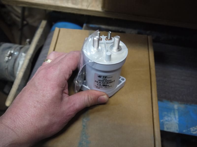
I'm building a high energy off-grid power source. It has lithium batteries. Of course the finicky lithiums cannot be over charged or over-discharged or charged when too cold (on pain of death to lots of things including one's wallet) The system's Battery Management System (BMS) needs the ability to cut the power to and from the batteries. Commonly used for this are the typical power solenoid relays:

Battery_Solenoid_wwa5b4.jpg


But those are abhorrent because they consume a ton of energy just being kept closed. They typically are too hot to touch making them scandalously power wasting. Not doing that.

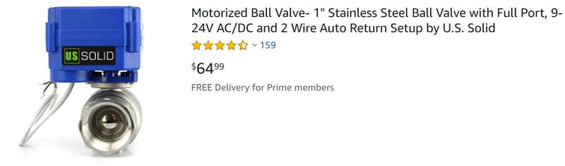
Much much better is a motorized disconnect that ceases to draw any power after it's open or closed.
I use these cool valves frequently. Look at the price for a stainless steel ball valve version!!

Motorized_ball_valve_cuet38.jpg


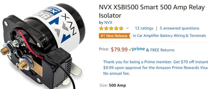
Amazing! So now turning to switching electricity instead of water, a much more trivial effort made of some stamped metal contacts and a little bending of it and you get this:

DC_motorized_Disconnect_hte6wh.jpg


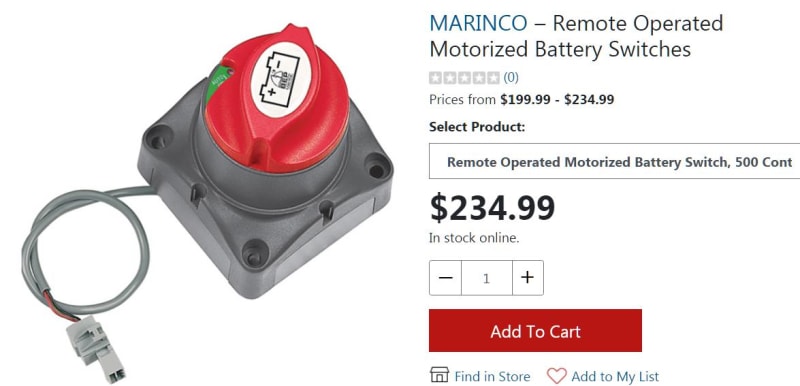
The problem is that ridiculous price! I'm not doing that. I need about 10 of these. But damned if I'm paying that exorbitant price for it.

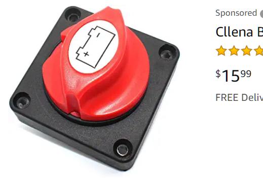
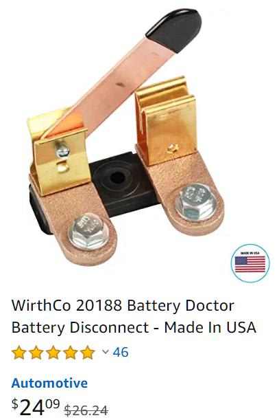
Here's the non-motorized price.
manual_switch_yhr83b.jpg


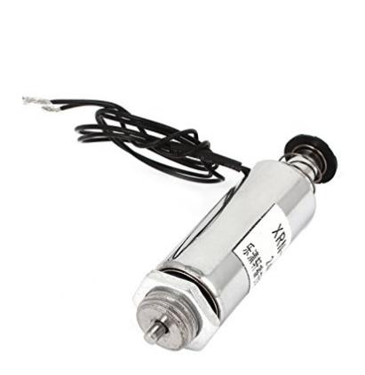
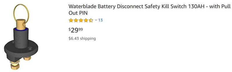
While OFF and ON would be nice I can live with OFF only. This means a solenoid type action where a PLC generates a brief ON could maybe pull something. Perhaps something like one of these kill switches.

Kill_SW_qf5eko.jpg


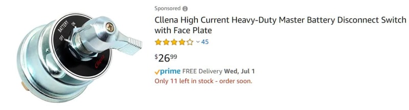
Or perhaps twist something like one of these:
Chrome_Disc_SW_mcyixj.jpg


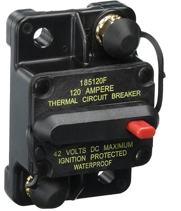
Or pulls open one of these:

KnifeSW_cgvcho.jpg


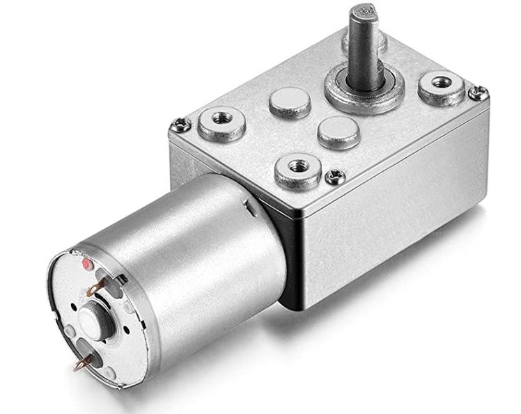
I could run a motor too.
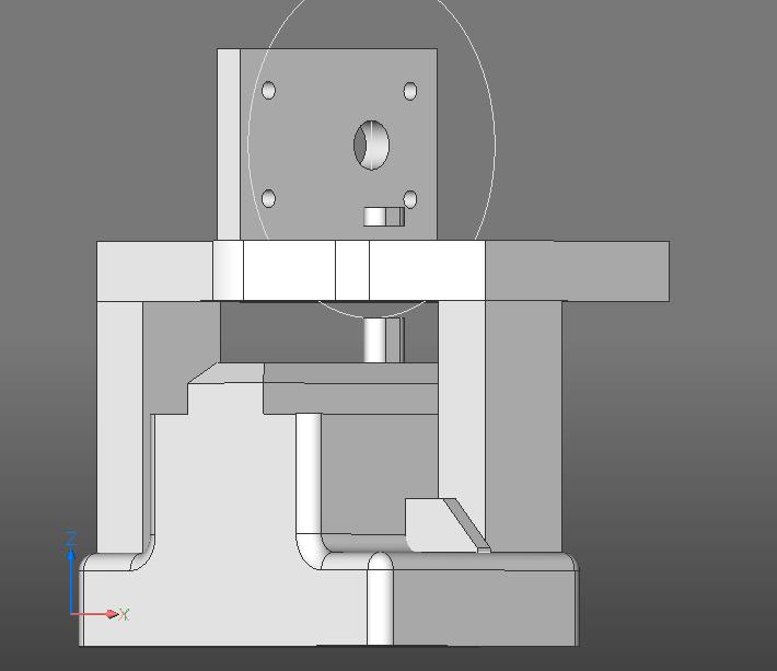
I have a couple of 3D printers and I'm not afraid to use them :) I can print most any cam, lever, shaft, housing, frame, linkage, or mechanism.

Suggestions?


Keith Cress
kcress -
 
Replies continue below

Recommended for you

I've started to design something but have come up against a problem I'm hoping one of you mechanical designers can help me with.

The plan was to use this breaker:

breaker_185_yu78h6.jpg


And, for an automated disconnect, poke the disconnect red button with this solenoid.

solenoid_swihxs.jpg


Turned out the red button takes a lot more force than I recalled. So much that the solenoid seems about 10% short of what it takes.

Bright idea! It's stroke is twice what the red-button distance needs to trip. I'll just swap that excess stroke for greater force using a lever. I'm so smart. DOH! @#%^!@* a lever reverses the direction of motion! Dang it. That would require the solenoid to be oriented down into the circuit breaker and would be too long to even fit...

Me need more force.

I decided to go with a tiny gear drive motor. Taking a 10,000rpm motor and reducing it to 45rpm, that'll buy you some torque.

gear_drive_xutymi.jpg


So I designed a bolt-on table to go over the breaker holding the gear motor. I'd use a disk with a high spot (cam) on it to rotate around sliding over the red button to push it. Once the lobe comes back up it would hit a micro switch that's in series with the motor killing the motor. To activate, the PLC would shunt the micro switch for long enough to get the lobe off the switch and the cycle would proceed to completion,(same as windshield wipers). If a human walks up they can hit a manual shunt switch that will also start the cycle.

The gear drive goes on the upper wall with the disk/lobe dropping down thru the table top to ride across the red button.
(ignore the button piece above the table it's just a 3D construction aid)
front_view_breakertripper_dyzgw5.jpg


Top_view_breakertripper_zwn0gj.jpg


PROBLEM. The geometry is sucking for this method as the disk/lobe will be so large as to cut the table in half destroying the table bridging and all related strength and stiffness. Also, I'm dubious that the sliding disk across the hard-to-push button may not play well.

Today after thinking about it I believe it makes more sense to use a little disk/lobe that all resides above the table-top and bears down on a shaft "push-rod" that carries the vertical force down to poke the red button without any lateral translation at the red button's surface.

It should be spring returned and so sit up until the lobe comes by and presses it down then following the lobe back up.

Is there any OTShelf components like that and if so what are they called?


Keith Cress
kcress -
 
re your first thought - a lever doesn't have to reverse direction: pivot near the end, breaker near the pivot, solenoid further out (both breaker and solenoid on same side of pivot).
 
Have you check to see if the red button is an interrupter or a reset?
It may be both, but.....
Is it snap action or slow acting?
If it is slow acting, you may end up building a task specific arc machine, the specific task being destroying contacts.
How about mounting the solenoid horizontally and having it pull an inclined plane across the actuating rod?
Or mount the solenoid horizontally and drive a bell crank.
Can you find a solenoid that takes a lot less current than a power relay?
Have you looked at lighting contactors?
Some models have latch and unlatch, momentary coils.
They are probably out of the budget though.

Bill
--------------------
"Why not the best?"
Jimmy Carter
 
Dan: Been over this. I'm not paying $3,000 for ten relays. I have multiple 3D printers and I know how to use them.

Brian...; Dang it! I didn't think of the 'crowbar' method. I shall consider it immediately to see if it fits.

Bill; Yes. I've used these Bussman breakers a couple of dozen times. The red button interrupts and when it does a sluggish lever drops out directly above the "42 Volts". You shove the lever back up into that ridge-body to reset the breaker. When you push the button it contemptuously oozes down and at about 1/2 the stroke distance the lever starts to drop. It stops anywhere you stop pushing the button, giving the amazingly bad impression that the contacts would be separated by only some tiny arc-supporting distance until the lever is fully deployed.

As measured from button top to the flat top of ridge.
0.283" free
0.159" lever starts to drop
0.090" lever fully dropped

To answer I'd call it all-ahead-slow acting.

When you reset it it feels like you'd expect it to when tripping. The lever rises until it's just about fully back up then CLICK! It snaps into place. Amazes me that it sluggishly drops without any feeling of release. Entirely un-breaker like.

I would perceive that either the cam or solenoid methods would be just as fast a human finger because your finger greatly deforms as you press the recalcitrant button.

Relays are out, see 'Dan' response.

Keith Cress
kcress -
 
One warning: levers exchange force with distance. Double the force by doubling the distance.
And solenoids apply maximum force only at the beginning of the stroke. As they extend, the force diminishes (somewhat linearly) until the rod is fully out. The coil can't exert a force on it any more. There's usually a stop before full extension, so that the rod can be pulled back in again.

So your solenoid will need to travel 2x as far to actuate the lever. The force it exerts may be 1/2 as much at that distance. Approximately.


Out of the box:
Arrange your breakers side by side and run a long shaft over all of them.
Put a cam over each breaker so that all the breakers operate together.
Arrange the shaft to make one turn and then stop.
Now comes the out of the box.
Lift the shaft about 1/4 inch or however much is needed to clear the breakers.
Us small solenoids to put spacer between the cams and the breakers.
Only the breakers with solenoids energized and the spacers in place will trip when the shaft rotates.
It's fun mental exercise to come up with new ides even if they are never used.

Bill
--------------------
"Why not the best?"
Jimmy Carter
 
Hi Spar;
That solenoid as seen above (the one in my possession) is actually what's called a "pull solenoid" though that doesn't make much sense to me. At any rate it pulls the slug into the core so it has maximum force when finally centered with the C-clip end against the body. That happens to extend the pushing tip to its maximum. If I energize it I can then push the red button with the end and get the red button pushed about 80% before the solenoid core pops out the back unseating the slug. So I think that will work for this force-distance wise.

That damper thing looks pretty good, too bad it's 24VAC and all I have is 24VDC.

Bill; That's definitely out of the box!

Keith Cress
kcress -
 
Seems like you already ate up the $2500 you were trying to avoid spending by designing something different....you must be making more than one of these.
 
Thank you for fighting the good fight!

I guess the mechanically latching contactor is an idea that doesn't work at this size.

Note also that you need magnetic arc-snuffing for DC loads this large, unless I'm mistaken.

My EV project came with a 48 V coil contactor with a coil economizer arrangement, i.e. it draws less current to hold it in than to pull it in in the first place. The Curtis inverter takes care of driving this coil for me. It also handles pre-charging of the inverter's input capacitors.

My main disconnect is a 500 A DC rated circuit breaker, that you can pull via a manual pull cable. A solenoid would pull it to the tripped (off) position easily enough, but it would take a manual reset. My pull cable has a solid "cable" inside a very spiral housing, so it can push/pull with a lot of force.

P1020303_eu5v4i.jpg


[img
 
Have you checked out Stock Drive Products? - They have all sorts of little cams and things that can push your little red button (or give you ideas to 3D-print your own). #6 wire under high deceleration is pretty good at pushing those too (some know this all too well in FIRST robotics).

Put the cam on a planetary gearbox output and you'll press it without issue.
Z
 
Hiya Molten! Nice contactor you got there.

I've found that while you'd think vehicle equipment running the same amps as stationary house equipment they could be shared but it doesn't actually work very well.

An example is your contactor. Even with an economizer that relay is a problem. On a vehicle that roars thru 45kWhrs zipping to work and back the economizer relay's consumption is nothing compared to another degree depression of the go-pedal or driving 68MPH for a hundred yards instead or 67MPH. The relay is only engaged the 35 minutes you're driving.

Now comparing that to a stationary solar powered facility that relay is going to be ON 24/7/365 the endless economized power draw becomes ridiculous, demanding extra solar panels and deeper daily discharge cycles.

It's annoying when you find things like your relay then start doing the math and...dang.


Zapped; That is a whack store! Weird and interesting stuff. I'm working thru it. Thanks.

Keith Cress
kcress -
 
A solenoid pull on that 2nd image (the DC rated 500 A circuit breaker) would do the job for you then- no on-state power draw, and only a momentary power draw to get you to the off state. But it would require manual reset.

I know the solenoid's continuous draw is a factor for a solar-driven system and no biggie in my car project. 25 yrs ago or so, a friend mine and I were looking at solar and wind-driven site remediation equipment. Just running an 8W solenoid valve coil continuously was a major cost- 1/2 W solenoids weren't a "thing" then, and shouldn't be a "thing" now either since the tiniest piece of teflon tape can keep them from actuating... One thing we did clue into is that the battery-operated mass market programmable thermostats have some sort of latching relay in them, so they don't draw current from the batteries in either state, just while changing state. They're not solid state- you can hear an audible "click" when they turn on. Otherwise, even a tiny relay coil would deplete the couple of AAs they have in them in less than a year. They made very good time scheduling devices for anything solar driven. There are similar 12V programmable timers available cheap from China via AliExpress these days, driven entirely by an internal "permanent" battery, presumably a primary nonrechargeable lithium battery. I've used them to schedule the landscape lights, fountain pump and automatic watering pump that I run off my solar/battery system.

The whole thing is backed up by the low voltage protection provided by my solar charge controller- that device keeps the battery from ever being over-discharged. Of course the cheap ones have several different types of lead-acid battery settings, but no adjustable high and low voltage trigger points suitable for protecting any Li ion battery type other than LFP. And though you can get away with a single high and low voltage cutoff if you're only using 3 NCM or 4 LFP cells in series, you can't get away without individual cell voltage monitoring for charge/discharge control beyond that- in fact even for 3 or 4 cells, individual cell voltage monitoring is still a lot safer in case imbalance develops over time. Even better, you don't want the whole thing charged to 3.7 or 4.2 volts per cell all the time if you want your cells to last- you want to stop lower than that!

Best of luck with your project- keep us apprised with your solutions!
 
Can I throw out a thought?
Have you looked at the power lock operators on an automobile?
Not to use, but the concept.
A solenoid has a small force at the beginning of its stroke.
A PM motor has its highest torque at standstill.
A motor is bi-directional.
A typical power lock operator uses a PM motor and a lead screw or jack screw.
How about finding a suitable breaker and then using a lead screw and small PM motor to open and close it?
Another option may be the latching mechanism from the rear hatch of a large SUV.
Our old Yukon has a mechanism that, when the rear hatch is close to the closed position, grabs it and firmly pulls it in to the latched position.
It has a lot more power than the common door lock operators.

Bill
--------------------
"Why not the best?"
Jimmy Carter
 
Gees Bill I bet both those would be applicable.

I'm very close on my attempt. There is a drive rod I just don't have the length right on yet. I printed 9 versions (including scaled versions to avoid an interference fit) and was very close last night when I had to pack it in. Not sure where my length math went wrong but since it's trivial to print a few more rods I woke up deciding to print a bunch with 1mm differences. They take about 5 minutes to print being pretty small.

Keith Cress
kcress -
 
Status
Not open for further replies.
Back
Top