Continue to Site

Eng-Tips is the largest engineering community on the Internet

Intelligent Work Forums for Engineering Professionals

  • Congratulations cowski on being selected by the Eng-Tips community for having the most helpful posts in the forums last week. Way to Go!

Lumber truss plate repair details 1

Status
Not open for further replies.

CivilSigma

Structural
Nov 16, 2016
106
Hi everyone,

Would you be aware of guidelines on truss gusset plate repairs?

I have a metal plate connection between a top chord and a web member than needs reinforcement, and I need to design a gusset.
Is it as simple as nailing the required amount of nails to carry the internal member force?

Any insight is appreciated. Thank you.


Replies continue below

Recommended for you

When I first started engineering, I designed many wood trusses with plywood gussets (50 years back)... We used Stelco hardened truss gusset nails... I don't know if they are still available. You connect the web members for full load, and the gusset to the chord are connected for the component of force in the direction of the chord (assuming the chord is continuous) If the chord component is 20K in one direction and 30K in the other, then you don't need to connect for 50K... only the difference 10 K.

Dik
 
I recall working on some tests using steel nail plates.
The design required using about 1/3 of the holes, but we also built some using 1/2, 2/3, and all of the holes.
The more nails the stronger they got (as long as you didn't splinter the wood). We even nailed some with the nail heads overlapping.
There used to be a number of people making plates and nails for this use.
Dik, were you designing with metal plates or plywood? I worked summers as a draftsman for a structural (mostly trusses) in the late 70's.

= = = = = = = = = = = = = = = = = = = =
P.E. Metallurgy, consulting work welcomed
 
Simpson Strong Tie makes a couple of different kinds of truss mending plates, one with teeth which have to be pressed on with a hydraulic press or C-clamps and one with nail holes. Repairing a roof truss in place is not quite the same as building a truss on the flat. Care must be taken when hammering sideways on a truss; impact can cause damage to other parts of the truss.

BA
 

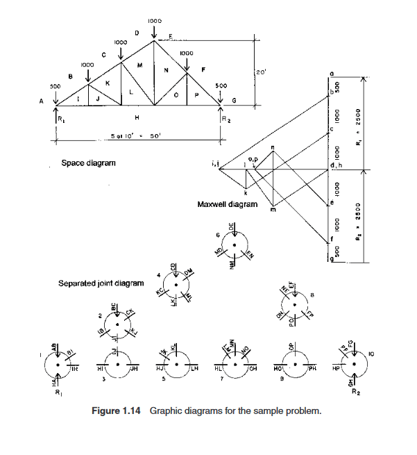
With plywood... most of the work was for Hudson Bay Company northern stores... in the middle of nowhere. Typically 1/2 Doug Fir... Predated TPIC by a decade or more... Used to graphically analyse the trusses (called at the time, a cremona diagram)... predated electronic calculators by a few years.

Dik
 
dik,

a cremona diagram
, was that graphic method by connecting force vectors? I started with that for truss analysis.
 

yup... used to draw the trusses and gussets also and provide a layout for cutting them out on a 4'x8' sheet of plywood...

Dik
 
:) :) Looking back, the work on old days were tedious, but simpler.
 
In the mid 1950's, I too used the graphical method to solve trusses. In fact in 1955, the City of Toronto required it to be shown on the structural drawings. Funny though, this is the first time I have heard the term Cremona diagram.

BA
 

YOu mean that computers haven't simplified things... I've noticed, over the decades, that engineers are making less money, doing more things, and are exposed to greater liability... we're really quite a clever bunch.

BART: That's what it was called... the other tech I worked with was from Brazil and the employer was Paul Krauss from Germany. I've never heard anyone mention the diagram other than at their office and that was the early 70s.

Just did a google search:


and it's there...

Dik
 
Computer helped to wipe out a bunch of good/solid engineers, but free up our hands to be "more productive" in many ways, and speed up the exploration of fantasies that were untouchable before... Don't get me wrong, I am quite efficient in computer, and do enjoy the convenience it brings, but sometimes I couldn't stop to wonder that, are we commending the AI, or the AI is leading our way of thinking. I couldn't recall when was the last time I solved a problem, or drew a sketch, on the napkins in the cafeteria :)
 
dik,

Your reference mentions the Maxwell-Cremona diagram. Now I remember, we called it the Maxwell diagram or sometimes just the force diagram. And the following article mentions Bows notation which I remember using.


In particular, the sketch below brings back fond memories. Simply scale the vectors on the Maxwell diagram to give the force in each member with as much precision as anyone needs.

image_yh0dyo.png


BA
 
Yeah, we call it "force diagram".
 
Status
Not open for further replies.

Part and Inventory Search

Sponsor