Continue to Site

Eng-Tips is the largest engineering community on the Internet

Intelligent Work Forums for Engineering Professionals

  • Congratulations KootK on being selected by the Eng-Tips community for having the most helpful posts in the forums last week. Way to Go!

Miami Beach, Champlain Towers South apartment building collapse, Part 05 111

Status
Not open for further replies.

SFCharlie

Computer
Apr 27, 2018
925
 
Replies continue below

Recommended for you

Thermopile, I can't prove anything? Pretty sure every single structural engineer in here has said that it started at the bottom, and I trust their judgement. They can feel free to correct me, but I'm pretty sure this is a fact now. That crack is on the opposite end of the building from the collapse, so I guess I don't see how it's relevant. Someone also suggested it was a cord or just a crack in the facade, which would match what MC said in the 2018 report too.. they had cracked stucco. A crack doesn't really prove much at all if you ask me.. this building had cracks all over. That hypothesis that Teguci posted is really worth reading over.

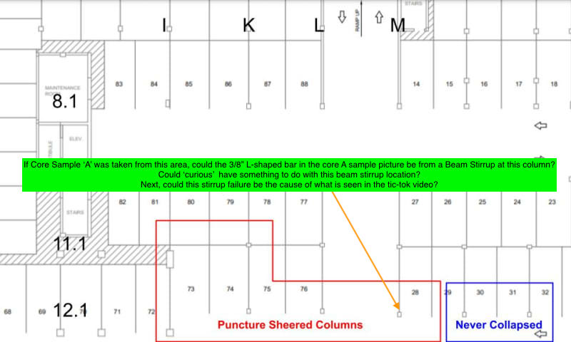
Js5180, Nothing in that photo lines up because it's underneath all of the rubble. Perhaps I should have drawn the line on the ground so it was easier to visualize instead of where the slab used to be.. but it's under the rubble in that pic. The planter is next to and behind column 28/M12.1 and something is clearly blocking the view to it.
 
Sorry if I was wrong about location of crack, as now I can see it is not in the area I thought it was. So irrelevant to collapse but serious maintenance issue. Look at crack on Memphis bridge tie girder, and how they reacted to that elevated crack.

Picture is opposite hand of area of interest. Perhaps, old eye-brain function. But theory still valid and remaining green tarp or bag is in right spot.
 
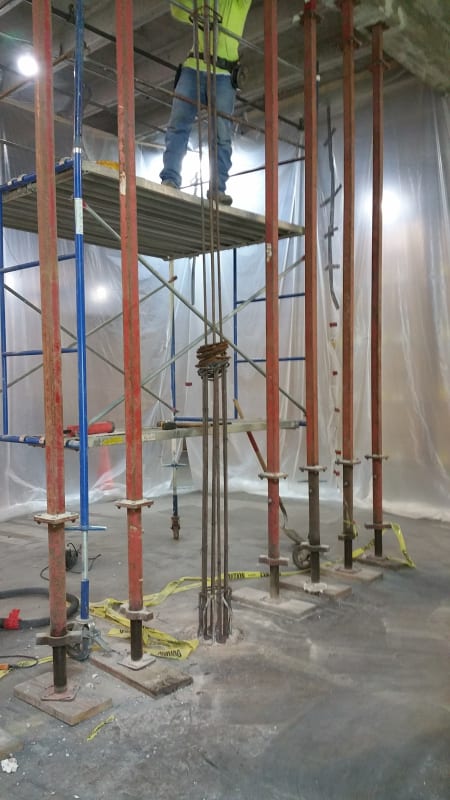
For what its worth, I've seen a 12" Dia concrete column taken out by a forklift (higher mass, but lower speed than a typical car). Photo from during the repairs. I'm skeptical of the car crash hypothesis in this instance, but there can be some plausibility to that.

20180703_122401_tfhkoo.jpg
 
And it is typically a point of local maximum moment for a column, if not the floor as well, so continuity through each member is normally highly desirable.

 
Js5180 said:
Electrical folks - good info on the phases.

I'll try to answer your questions but I have not seen the electrical drawings and it seems that spsalso has so I will use the info he posted and my real world experience.

The building probably had 480/277 service for things like fire pump, domestic water pumps and pool equipment. 277v could have been used for house lighting. Then they would need a large transformer to provide 120/208v three phase. This would be fed to sub panels throughout the building. The sub panels each fed two floors of apartments above the 2nd floor. The 2nd floor panel MAY have fed a service panel for house lighting and general use receptacles for all floors so you can't use a sequence of lighting outages to help determine how the building failed.

Each sub panel would feed an equal number of units with a two pole breaker giving 120/208 "split phase". The phases are 120 degrees apart instead of 180 degrees and that is why it is 208v and not 240v. You lose efficiency for loads like water heaters and ovens but save on needing more transformers.

You can never balance the loads completely because some units on the same phase may be unoccupied. The best you can do is feed the same number of units on each phase and monitor usage to see if you need to re-balance later. With 24 units being fed from each panel you would feed 8 of them from a two pole breaker on A and B phase, 8 from B and C phase and 8 from C and A phase. That gives you 208v for each and then add a neutral for the 120v circuits.
 
Kudos to Teguci for taking the time to throw some schematic analysis at the plaza-level slab deterioration theory. It's not as sensational as the roof-level theory that seems to continue to pervade the conversation, but certainly most plausible in my mind.

 
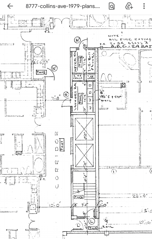
Where are the plumbing chases? I'm wondering if they were a failure node.
Fire water supply piping should exit out of the generator room and do a vertical run. The dryer vents, not sure what path they take, where they are.
I just wonder if that's a roof-basement weakness or path. Some fire-proofing was going to be added at each floor and not sure if there is concrete there.
 
Js5180 said:
Electrical folks - good info on the phases.

Could the units be split-single phase, or would this require an extra transformer on each floor?

The main answer I’m trying to get to is how many different phases - that is, 120 degree phases off the 480 system - left the electrical room on each floor, and in what combinations.

Most apartment panels in a 120/208V 3P4W system will have 2 hots and a neutral. These will get staggered in the meter bank, e.g. Meter 1 is L1L2+N, Meter 2 is L2L3+N, etc.

More importantly, though, is that the runouts (and sometimes the risers) from meter banks to apartment panels are very frequently run in flexible metallic conduit (FMC) in a drop ceiling, soffit, or other interstitial space. Unless someone can conclusively prove that all the apartment runouts were piped in EMT, you really can't, and shouldn't, read anything at all into the timing of the lights going out.
 
lucky555 said:
Fire water supply piping should exit out of the generator room and do a vertical run.

Yes. They exit the generator room and go through the parking level to the stairwells where they are protected and still accessible for testing and maintenance.
 
OK. Great, because I'm beginning to think it started with a transformer explosion.

NOT.

 
It's not unusual for a fire pump to have its own eletrical service seperate from the rest of the building. Generally overcurrent protection is not allowed upstream of a fire pump controller.
 
Teguci's post about the design/deterioration really explains every single video and fact perfectly. It seems like the slab he's describing is the one you can see laying on the garage floor in that tiktok video too. The north building also doesn't seem to have this same design flaw even though they were supposedly built with the same plans. You can see this section of their garage at 3:31 in this video -
He never looks at M10.1, but on the left you can see M11.1, and M12.1 at the center of the screen. There is no beam connecting M10.1 to M11.1 in their garage, and no step in between them. Instead the step seems to be sitting on M10.1. Or perhaps there's a soffit or a drop ceiling covering it there? If not, it does make you wonder if they noticed the flaw in between the two buildings and then tried to fix it on the north one.

I think the curious thing MC noted was that the building slab actually did have a slope to it when he tested it in 2020, but in 2018 that was his best guess for why it was so deteriorated within the garage. It's brought up a bit in those board meeting notes in 2020, and it says that he was going to need to test the slope further. It makes sense that the design problem was actually much more complicated than that.
 
1503-44 said:
OK. Great, because I'm beginning to think it started with a transformer explosion.

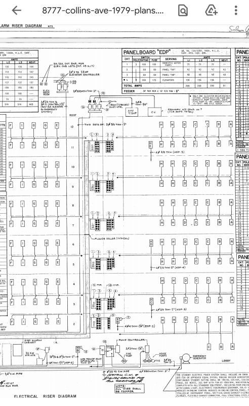
What evidence do you have for that? The electrical riser diagram (page 83 of the big PDF) has the entire building on 208V 3 phase, unless I'm missing something, so there shouldn't be any transformer other than the main one beside the service entrance. That part of the building survived the collapse without much damage. The subsequent fires in that area might have come from that transformer vault, possibly, but that's secondary to the major collapse.

It was between column lines C and D, and between row 1 and 2. That's the far west segment of the northern exterior wall. Nothing I have seen points to a transformer explosion there, or anywhere else. It's a long way away from K–M on the 9.1 row.
 
Hi! I just joined, and wanted to share what I saw about the electrical system in the plans. I'm not an expert by any means though.

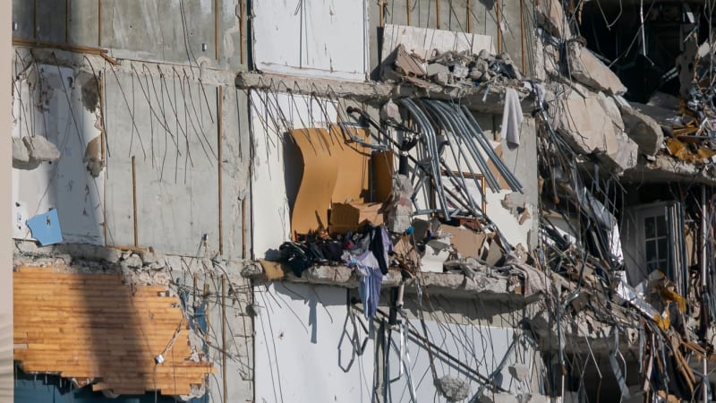
It looks like all the electric wires come up from one place, then go horizontal through the even numbered floors. The plans have a meter room on some floors, and in pictures you can see what looks like 12 conduits coming from the shear wall where the meter room should be, on the even floors as the plans predict. So the x10s and x11s should have lost power as soon as the slab broke from the shear wall.

Page 58
p58_1_jl4fsk.png


Page 83
p83_1_tohqgb.png


conduit_hevn0x.jpg


conduit3_z01wr4.jpg
 
jbourne8 (Computer)12 Jul 21 08:48 said:
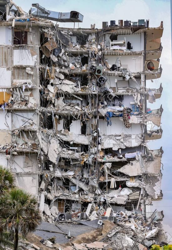
what else could possibly cause this sort of destruction down there
Yes! That's the $300M question.

Sorry, I still think the Patio Table looks an awful like the ventilator from the garage roof

SF Charlie
Eng-Tips.com Forum Policies
 
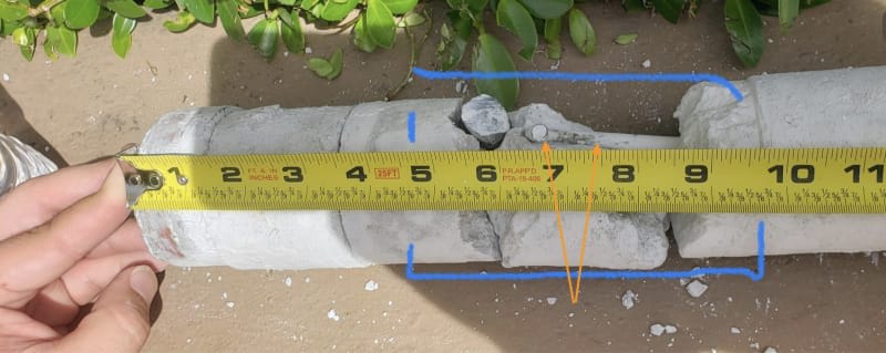
Sorry, I picked wrong diagram. I mean M-11.1 for core sample A.

I give up, I am out. I can not keep facts straight when looking at pictures....

Old Age Sucks!

Please don't everybody clap at once.............
 
SFCharlie (Computer) said:
Can't even read the sign on the gate, and we know what that says...

That's an excellent point. It's a level of detail on a small level that is known from other sources (not the frame from tictok rendering that I have seen). You can infer something from any attempt to enhance detail using that as a reference.
 
Status
Not open for further replies.

Part and Inventory Search

Sponsor