Eng-Tips is the largest engineering community on the Internet

Intelligent Work Forums for Engineering Professionals

  • Congratulations waross on being selected by the Eng-Tips community for having the most helpful posts in the forums last week. Way to Go!

Miami Beach, Champlain Towers South apartment building collapse, Part 07 90

Status
Not open for further replies.
Replies continue below

Recommended for you

As for lessons learned, that is premature. Until we can isolate the reason for failure, we can't address it.
 

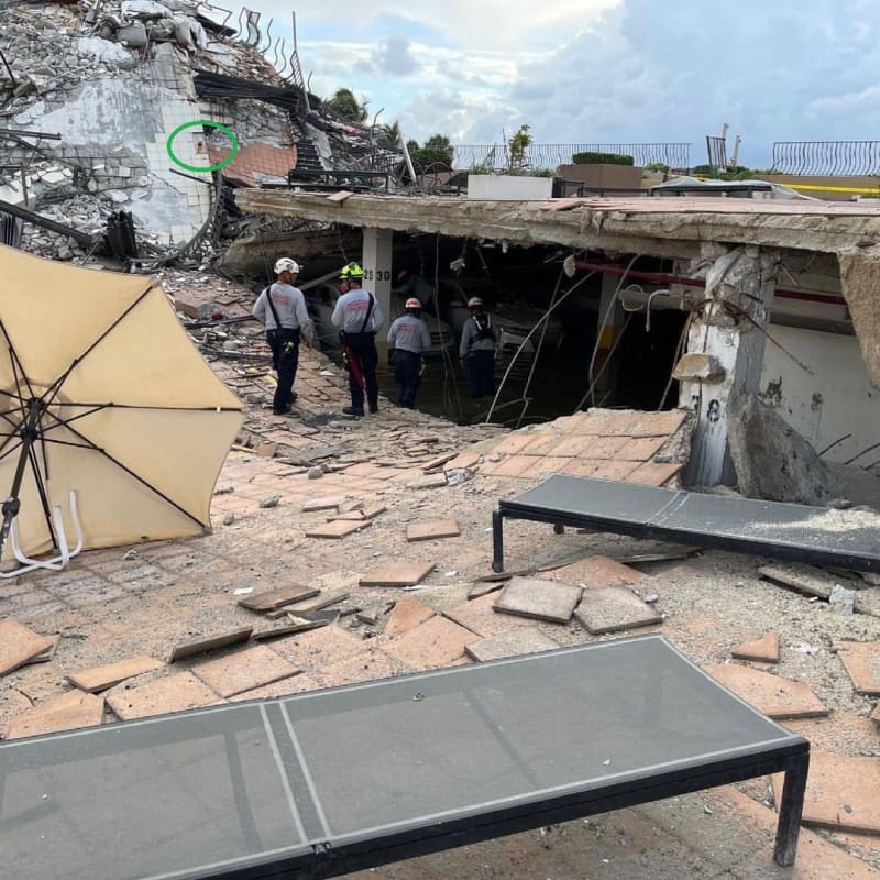
You make several good points. We engineers who do this type of work regularly see deteiorated reinforced concrete members that look a lot worse than what we can see in the 2018 report and in the video of the parking garage taken by a prospective buyer a year or two ago. The beam you are referring to as the possible initiator of the collapse can be very clearly seen in the parking garage video. Although the beam appears to show some curvature (most likely due to deflections during casting), it does not show the type of structural distress that we would typically see as indicative of imminent failure. This is why I lean towards the theory that a section of parapet fell off the roof and impacted the column and/or beam.
 
Wouldn't it have been interesting to measure the lateral movement in the E-W direction over time, and during a hurricane event versus steady state???
 
This video is from a professor of civil and environmental engineering at Northeastern, and an expert in "progressive collapse" of concrete structures. He addresses a possible scenario for the Surfside collapse.

Link
 
You make several good points. We engineers who do this type of work regularly see deteiorated reinforced concrete members that look a lot worse than what we can see in the 2018 report and in the video of the parking garage taken by a prospective buyer a year or two ago. The beam you are referring to as the possible initiator of the collapse can be very clearly seen in the parking garage video. Although the beam appears to show some curvature (most likely due to deflections during casting), it does not show the type of structural distress that we would typically see as indicative of imminent failure. This is why I lean towards the theory that a section of parapet fell off the roof and impacted the column and/or beam.

My theory is that this beam was NOT failing prior to the collapse. It was just set up for failure. I have a project where the contractor didn't provide enough bolts at a beam to wall because the architect did not want to see the side tabs. This connection would have, likely, held up fine. UNTIL that portion of the structure became stressed to load for some reason or one of the bolts deteriorated, or a car hit the roof of the garage...

The trigger for failure could have been a falling parapet section. I wouldn't rule that out. I just feel it is more likely something as simple as damage that occurred due to a vehicle on the plaza or storage. I also cannot rule out the possibility that the plaza was saturated by the recent rains and the reason it was impacted more now than in prior weather events had something to do with the activities on the roof.
 
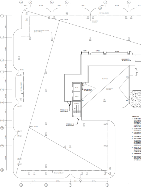
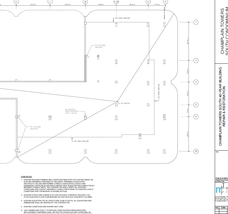
I haven't done a deep dive on the roof anchors, because I don't believe they're the cause, but to just answer some questions, it seems at least some of the roof anchors were installed and possibly split into two phases, because the drawings posted on the town website only show anchors on the east side/penthouse roof (basically the part that collapsed), but photos show other anchors on the part that didn't collapse, that are not on the drawings. Possibly an earlier phase of the project? I noted that the posted plans are called Phase IIB. Sorry if this retreads on past posts, like I said I've not paid much attention to roof anchors.

Capture1_zaczln.png

Capture2_b0jsx1.png
 
Teguci (Structural)20 Jul 21 16:40 said:
that is premature. Until we can isolate the reason for failure, we can't address it.
Yes, we need access to more information, (i.e. drone videos, etc.) information that the response team is holding very close to their chests.
I hope we can, however, discuss how to mitigate the propagation of the failure.

SF Charlie
Eng-Tips.com Forum Policies
 
For some reason, not all roof anchors are NOT on same drawing. It takes looking at two sheets to see them all. I can’t remember sheet numbers
 
Has it been determined what the blue spray painted items represent vs the red spray painted areas?

edit: nvm
 
Hi everyone, I'm a double E graduate, new to this forum. This collapse caught my interested.

I just wanted to point out one thing from the TicTok video that I haven't seen anyone discuss.

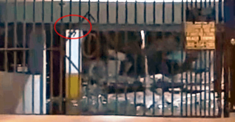
After reading this thread for a few days, I'm seeing a lot of evidence that m9.1 was the first column under the building to fail. It must have failed within a few minutes of the tiktok video since the building collapsed soon after. I took a closer look at that video for signs of failure, I noticed that the top of the column M9.1 was missing in the image. I almost fell out of my chair when I first saw it.

It's very possible it's just a video compression or motion compensation artifact. I don't see how it's possible for a column to actually fail in a even slice.


Screenshot_2021-07-08_at_11.42.49_AM_x4hrwd_bvun2a.png

Tiktoc_cropped_unzfig.png
 
Garage_View_mpxihp.jpg


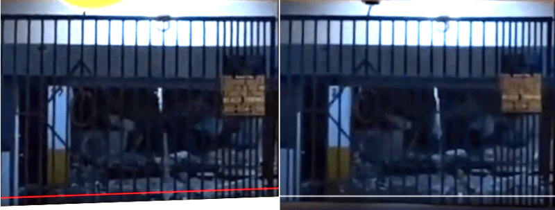
In order to obtain a 3D image, all that is necessary is to have two distinct views spaced approx 6 inches apart. There are two such views on the TIC-TOC video. So for what it is worth, here is a 3D view looking into the garage. In order to see the 3D view it is necessary to view this picture cross-eyed, such that the left image is viewed with the right eye, and the right image is viewed with the left eye. Best viewed from at least 18 inches away from the monitor.

There is nothing in this view that jumps out, but at least looking at it in 3D it is possible to discern closer items vs farther items. For example, the third column looks like its top half is obscured by the collapsed pool deck. For what it is worth, another view.
 
Yeah that's definitely something in the foreground, you can see it clipping the other column to the left as well. I think in the 2020 video tour there is a black PVC pipe running across somewhere there?

EDIT for confusing column numbering - the still visible columns appear to be 'M8', 'M9.1' and 'M11.1'. The 9.1 line is basically the same as the 10 line but not quite, and ditto 11.1 vs 12. There is no 'M10'.
 
@Demented.
A extra couple of hundred tons. Over 400,000lbs of flooring and kitchen cabinets and such were added to the units in the section where the collapse initiated?
 
Heck... I've designed foundations for transformers that weighed that much, and there were 6 of them. They are at grade level and cannot fall much further. [lol]

Rather than think climate change and the corona virus as science, think of it as the wrath of God. Feel any better?

-Dik
 
Reposting a picture that Demented posted earlier for a different reason. Look at column '38'. This would be column M/N15 (midway between column lines M & N on column line 15. It is just north of the spa and supported relatively short spans to the south and east because of the spa and pool. It looks like the structural slab punch sheared completely around the column, but the overlay, mortar, and tile to the east did not collapse. I believe that the piece of slab leaning on its south flank is just structural slab that separated and fell while the slab on the west side is everything up to and including the pavers. Notice the missing layer compared to the slab to the left (north) side of the column. Just eyeballing it, I'm seeing maybe a 5-6" structural slab, 4" overlay, and 3" mortar. That's a big difference compared to the 9 1/2", 2 3/8", and 1 3/8" thicknesses they found at the planters.

Also, I don't know if anyone has questioned the overlay. Was this part of the original construction or a later repair? If it was original, why? Is it possible that they sloped the slab to the south by just thinning it down. Perhaps the pouring crew assumed that it needed to be sloped, but the forms were level. After the mistake was discovered, they chose to overlay it to bring it up the the 9 1/2" spec. They started with a 2" overlay at the south side of the east wing, and it ended up being 4-5" think at the south retaining wall. They justified the thin structural slab as okay because it only has to support a few sunbathers and lounge chairs. I also don't see any top bar in that section.

I'm starting to think that the failure could have started at the south side of the pool slab where the slab was thin, propagated by punch shear to the stepped area, then moment loads from the unsupported patio slabs that are hooked into column line 9.1 resulted in weakening and eventually failing those columns.

column_38_ss2qsm.jpg
 
That 3D composite is a genius idea. I don't see anything much in it though. (I think you posted it wrong way around though?)

How come there are these 2 videos? Is one from Adriana and one from her partner? Did a single phone record the whole video in stereo?

The dark horizontal object along the 'bottom' of the debris looks significantly in front of anything else. It could be a piece of waterproof membrane or something edge on to us. It looks too thin to be a piece of slab though.

It looks in 2D like the white object in the middle overlaps it, but I think that's actually 2 different objects, one behind and one overlaid. The grating of the gate is really obstructive though. One can imagine a piece of sagging slab behind the water, sloping towards us, but I'm not sure if that is actually there.

The left side of the debris looks a lot closer than the right, consistent with a diagonal failure line starting over by the M line and implying that (at this early stage) L and K are probably not collapsed out of shot.

That's definitely a planter (well, a concrete box at least) where M11.1 should be. Couple of interesting things about that though
- It seems to be sitting directly on the garage floor, or at least only on a thin piece of debris. How is that possible? Surely it should be on at least the 9" of slab + toppings? Where is the M9.1-M11.1 beam which should also have been under it?
- One image (the one you put on the left) shows more debris in front of this planter than the other. It might just be a camera artifact, but the two images are very consistent otherwise. Does that debris appear during the video?

EDIT the thing which I've never understood about this video, and which this composite doesn't help with at all (because nothing obvious is blocking it), is why can't we see M12.1? We know that column still stood, and unless the pool deck has fallen and is completely blocking the shot, either the bottom of that column (beneath the deck) or the top (poking through in puncture shear) should be visible.
 
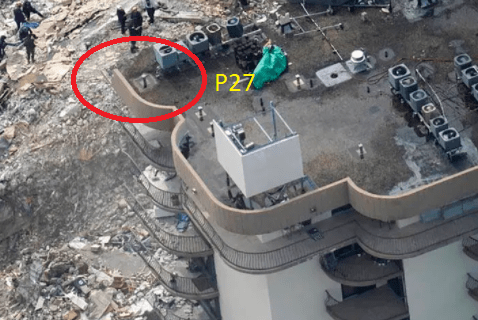
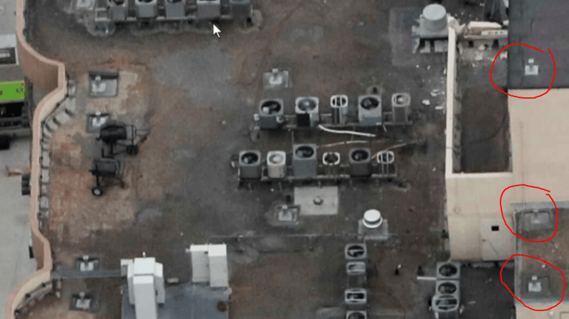
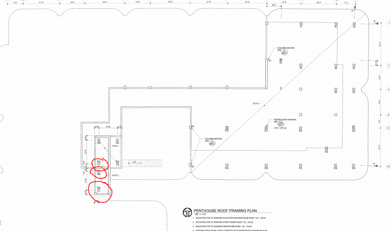
Something that continues to bother me about these roof anchors (as a total layman):

Some anchors are installed atop columns. But others are installed on the overhang.

This one in particular was closest to the edge of the still-standing portion and can be seen to be clearly on the overhang from other angles (Can't find a good picture at the moment)
anchor_p27_tu1t3f.png


Why not have anchors only over columns to ensure that the roof overhangs are not compromised in any way? Even as a layman it occurs to me that it is a bad idea to cut/drill/add weight onto a cantilevered structure. Of course if it is on the plans I would assume that the engineer had considered this...

Shots of the two sheets from the plans
western_w4qney.png

eastern_pflutl.png


Again very much a layman perspective, but as many others continue to point out the collapse happened after/during roofing work and anchor installation so it is not prudent to simply ignore problems coming from above.
 
MikeJ65 - good observations. The best I can tell from the original drawings is the structural slab was supposed to be flat based on only one uniform elevation given for it. The plumbing drawings showed sloping towards deck drains, I assumed this was accomplished with the sloping overlay over the flat structural slab. The architectural finish drawings called for the pool deck called to have simulated keystone, which I think was a the pattern stamped into the overlay. Lots of speculations of course - based on fairly undetailed 1979 drawings.

There are actually 3 layers on the structural slab from the Morabito core sample. Structural deck (they found 9.5" where they drilled), plus the overlay topping (original?), plus tile/mortar (renovation?) + waterproofing/sand/pavers (renovation #2?).

As for the slab failure in the photo, I agree with your observation. It seems like the slab continued to fail along a straight line of which others speculated is a construction joint separating the area around the pool with the rest of the deck slab, and whereas the topping above did not fail along that line. It also looks to me like the column has been pushed out of plumb possibly by the falling deck, but it's hard to tell with that angle. If it did get pushed by the deck, it might support that this happened elsewhere like near the building collapse.
 
I found this Briefing Map on Twitter, the legend is too blurry to make out, but notice the Black circled columns south by the pool and the sheer wall, also black crossed thru square.. Then there are blue dots spread out but they're not marked columns.
Can someone explain what the black circles and blue dots represent?

Link
 
Status
Not open for further replies.

Part and Inventory Search

Sponsor

Back
Top