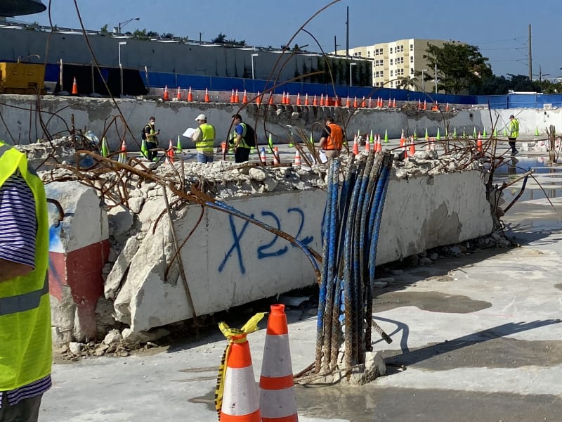
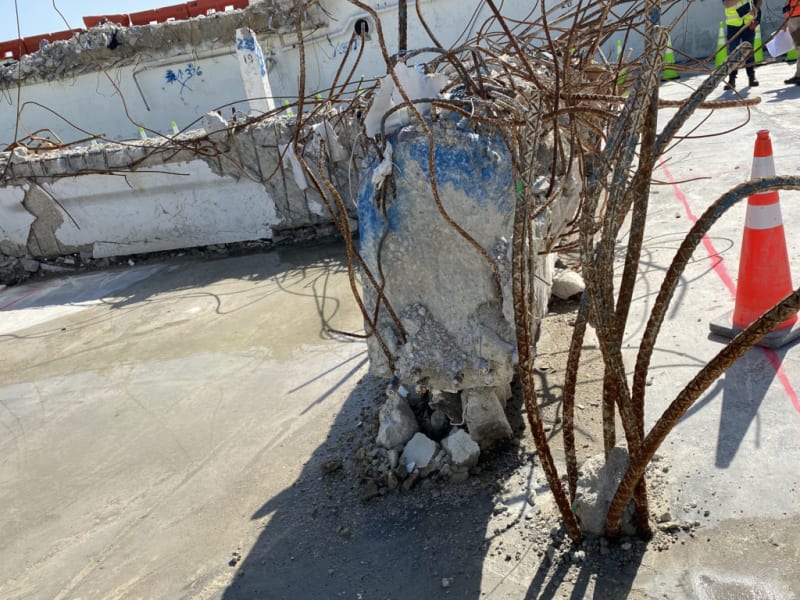
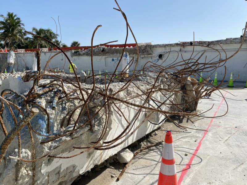
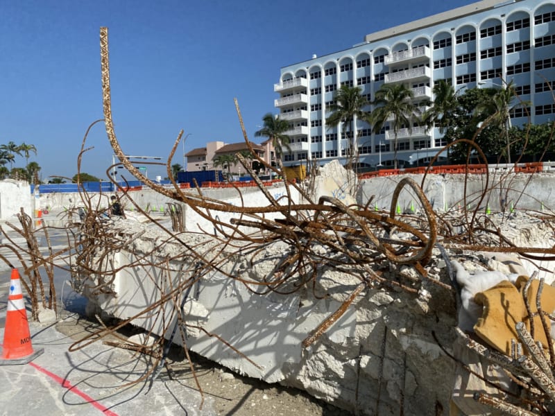
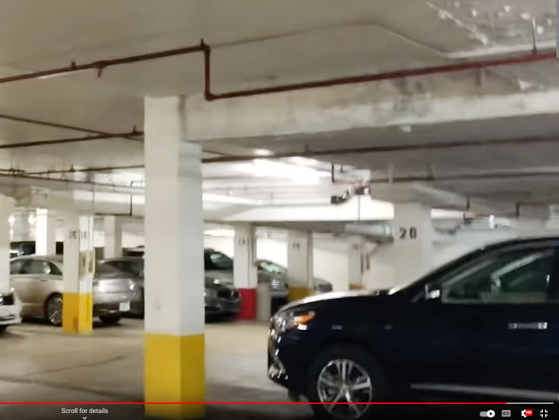
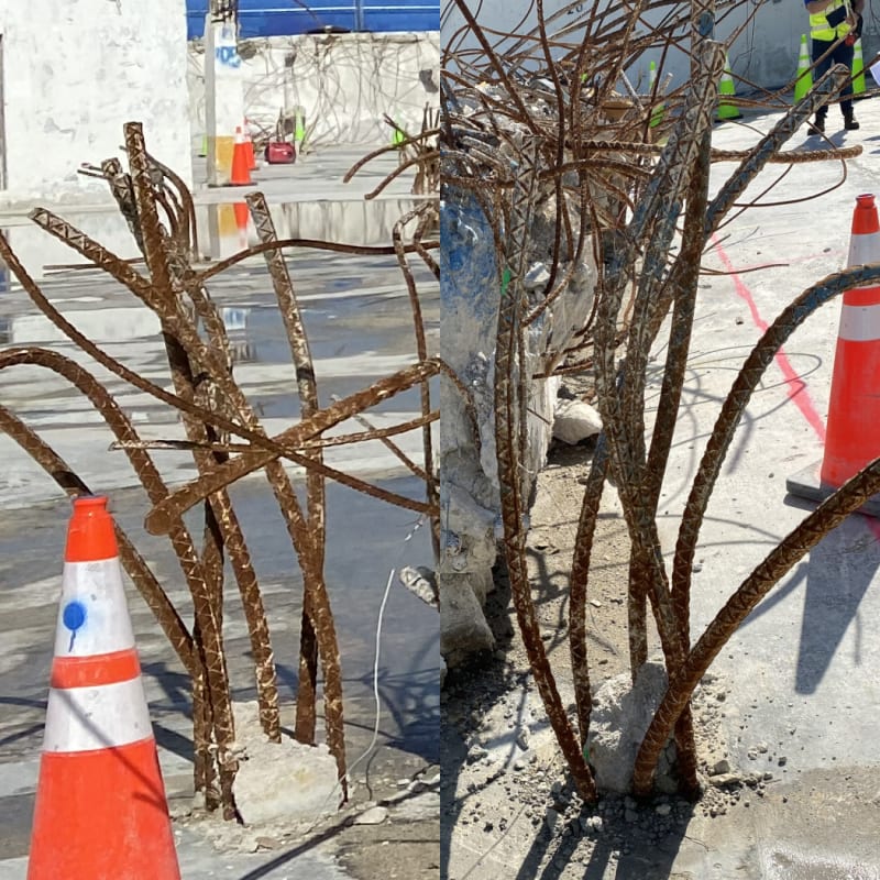
A continuation of our discussion of this failure. Best to read the other threads first to avoid rehashing things already discussed.
Miami Beach, Champlain Towers South apartment building collapse
Miami Beach, Champlain Towers South apartment building collapse, Part 02
Miami Beach, Champlain Towers South apartment building collapse, Part 03
Miami Beach, Champlain Towers South apartment building collapse, Part 04
Miami Beach, Champlain Towers South apartment building collapse, Part 05
Miami Beach, Champlain Towers South apartment building collapse, Part 06
Miami Beach, Champlain Towers South apartment building collapse, Part 07
Miami Beach, Champlain Towers South apartment building collapse, Part 08
Miami Beach, Champlain Towers South apartment building collapse, Part 09
Miami Beach, Champlain Towers South apartment building collapse, Part 10
Miami Beach, Champlain Towers South apartment building collapse, Part 11
Miami Beach, Champlain Towers South apartment building collapse, Part 12
Miami Beach, Champlain Towers South apartment building collapse, Part 13
Miami Beach, Champlain Towers South apartment building collapse, Part 14
Miami Beach, Champlain Towers South apartment building collapse, Part 15
Miami Beach, Champlain Towers South apartment building collapse, Part 16
Miami Beach, Champlain Towers South apartment building collapse, Part 17
SF Charlie
Eng-Tips.com Forum Policies

