Eng-Tips is the largest engineering community on the Internet

Intelligent Work Forums for Engineering Professionals

Miami Pedestrian Bridge, Part I 65

Status
Not open for further replies.

JohnRBaker

Mechanical
Jun 1, 2006
35,343
2
38
US
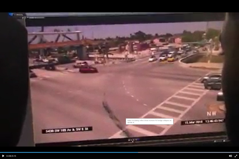
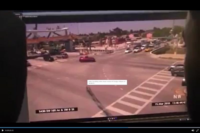
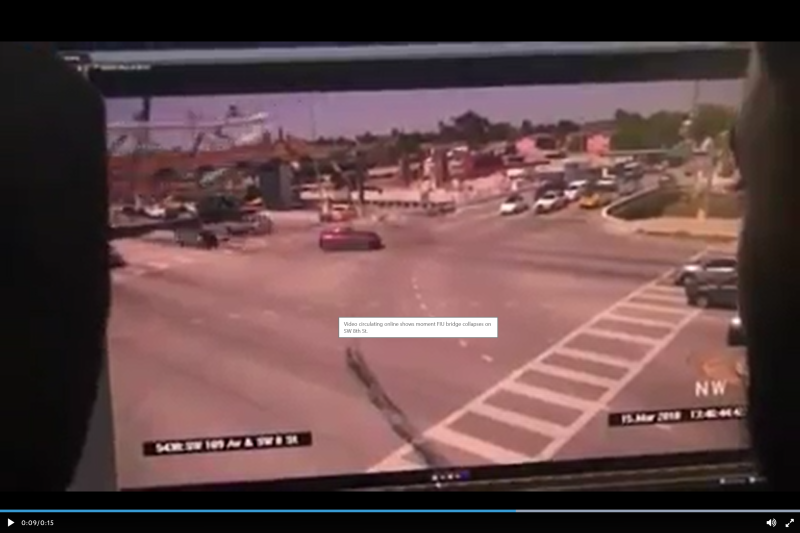
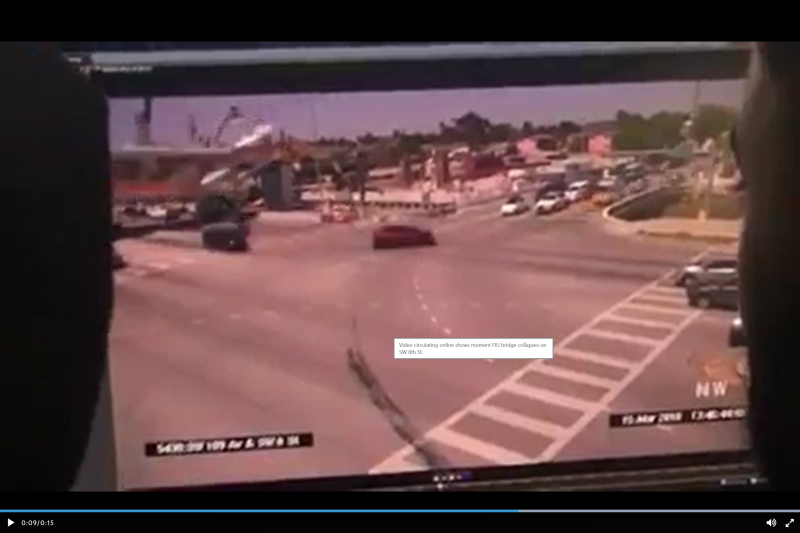
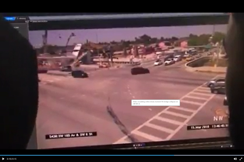
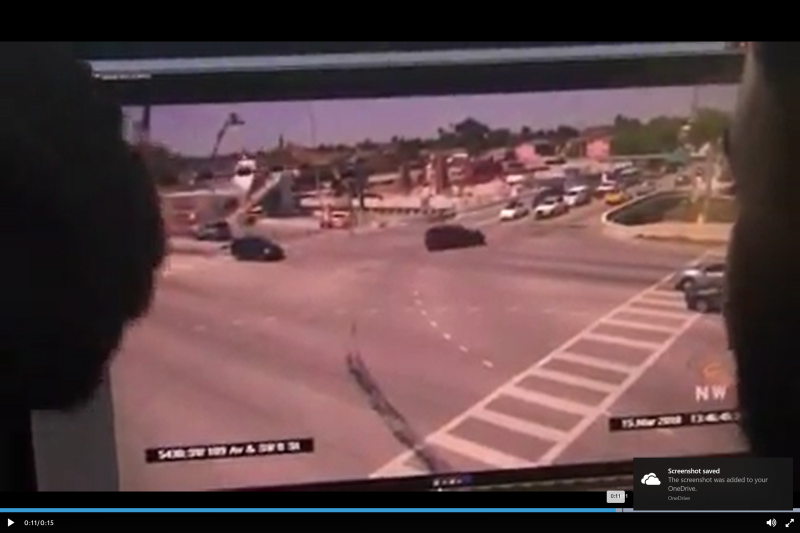
Multiple Fatalities After Pedestrian Bridge Collapses Near Florida International University


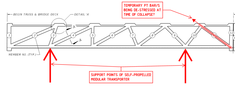
As investigators continue to search the site of a deadly collapse involving a 950-ton pedestrian bridge near Florida International University in Miami Thursday, officials say the death toll has risen.

Early Friday morning, the Miami-Dade Police Department confirmed that six people have died as a result of the collapse....

John R. Baker, P.E. (ret)
EX-Product 'Evangelist'
Irvine, CA
Siemens PLM:
UG/NX Museum:

The secret of life is not finding someone to live with
It's finding someone you can't live without
 
Replies continue below

Recommended for you

Break down of video:

Frame Prior to Collapse:

2018-03-16_1_uedqbg.png


Not sure if it is the video or if the first diagonal is buckled and maybe the section of top chord between the first diagonal and end of the bridge:

2018-03-16_4_l9hegx.png


First diagonal appears buckled and the bottom chord has collapsed:

2018-03-16_5_yjqv2z.png


Following Frames:

2018-03-16_6_lb2hji.png


2018-03-16_7_ysza8i.png


2018-03-16_9_dbgd7e.png


EIT
 
Well actually done that on a few situations. One school building and a timber stairway at the same college. Evacuated building and blocked off the stairway. One building shifting and making noises. Told people to get out and the building collapsed two days later. One 200 stiffleg derrick - told superior that the derrick would collapse. Derrick collapsed and injured a guy. One building where the roof was failing - family out and building official red tagged the building. One unsupported crane boom boomed horizontal to hold a canvas with people under tables eating. Got the fire department to stop it. There's more but it's over a lot of years.

Sorry for the rant.
 
RFreund - Saw that yesterday evening as well but later when I looked at it, the video may have played differently. I'm wondering if the work on the canopy was to De-Tension Truss No. 11 on the north end. They may have been there for more than one purpose.

The original proposal had both sets of the Self-Propelled Modular Transporters spaced apart. Starting on the south end (FIU) the first rig was planned to be positioned directly under the south end of the span & the next rig 24 ft to the north. At the opposite end, north (Sweetwater)/Pylon, one rig was again to be positioned directly under the north end of the bridge with the final rig 27 ft to it's south. As it turned out this plan was too wide for the road way and they may have encountered a hiccup with uniformly supporting the bridge when driven over the center divider. It looks like they still had trouble driving over the center divider, even with the tandem Self-Propelled Modular Transporter arrangement. They stopped half way across and just sat their for a long time. Since the Self-Propelled Modular Transporter was no longer under the ends of the bridge, I wonder if they decided to PT the No. 11 Truss, with the intent to De-Stress the truss once the bridge was in place. It sure seems like it took a lot longer than 6 hours to position the bridge. It looked close to midday when they we finished. Link
 
If anybody still thinks this was really supposed to be a cable stayed bridge, you should review the drawings as to how the pipes were to be connected. They were to be bolted to the concrete with end plates. That is not how you connect cable stays.
 
Hokie66 -- exactly.

(Also, regarding that professor, absolute garbage writing. Unfortunately, it seems he's rather effective at self-promotion. Same way we get our politicians)

OhioMatt -- absolutely. Design-build projects inherently have more aligned interests, which can mean more trust and fewer checks. That's part of the efficiency, but can also be dangerous if people work outside their competency or back down too early in the face of peer pressure. It requires the individual engineers involved to be that much more careful to act ethically.

----
The name is a long story -- just call me Lo.
 
hokie66 said:
If anybody still thinks this was really supposed to be a cable stayed bridge, you should review the drawings as to how the pipes were to be connected. They were to be bolted to the concrete with end plates. That is not how you connect cable stays.

Lomarandil said:
Hokie66 -- exactly.

And another "exactly" from me too.

16" CHS/tubes with bolt on connections - hardly your high-tech strand stay cables!

For those that wish to see the "PRELIMINARY 2015 - NOT FOR CONSTRUCTION" details, see the following:

CaptureM1_avtwtu.png


CaptureM2_iwti8h.png


Capturem3_cxdgnf.png
 
"Easy to say with benefit of hindsight, but concrete cracks, tendons detension, tendons snap, anchorages fail, and getting on with things is part of life."

...said NASA management. Sorry, if you are designing stuff that risks people's lives then 'shit happens' is not an acceptable standard of care.

Cheers

Greg Locock


New here? Try reading these, they might help FAQ731-376
 
minerlax4 said:
On page 115 of that pdf, it shows the tendon arrangement for the panel point on the opposite end. If you mirror that, the #11 tendon, assuming #11 has tendons, would protrude in the spot that matches the tendon in the photos with the jack attached. It also appears to be pointing toward the end bent in the photos. I agree it makes no sense to be tensioning #11 when it's already under compression. Maybe you're right and it is #10, though. That would make the failure more difficult to explain, but would make a lot more engineering sense.

On page 115 of the submittal the PT bar schedule details ZERO PT for compression member #11, which I assume is for the final spanning condition:

CaptureM4_ovnmd0.png


epoxybot said:
Since the Self-Propelled Modular Transporter was no longer under the ends of the bridge, I wonder if they decided to PT the No. 11 Truss, with the intent to De-Stress the truss once the bridge was in place.

I think this is most probable. During transportation/erection there was tension in member #11 so maybe they provided some temporary PT for this condition, and whilst this temporary PT was being de-stressed the collapse occurred. It is in keeping with the location of the stressing ram and de-stressing stool seen in the collapse photos.

CaptureM5_dhj93y.png
 
May be a dumb question, but can someone explain why the top flange has any PT strands at all?

If the cable stays are just for show, when would the top flange ever be in tension to require PT?
 
adamewood said:
May be a dumb question, but can someone explain why the top flange has any PT strands at all?

For during lifting etc? as per diagram immediately above.

Also for bending of the top flange.
 
Greg said:
Sorry, if you are designing stuff that risks people's lives then 'shit happens' is not an acceptable standard of care.

I'm not saying that. Just pointing out that cracks and tendon issues are pretty common in stressed decks and people don't generally hit the panic button unless it's out of the ordinary. Evidently this guy didn't think it was.
 
By way of summary of the PT that made up this bridge:

1. Transverse bottom-flange PT: 4x0.6" dia, 7-wire strands, GROUTED tendons @ 2'6" spacing. These tendons were fully stressed, capped and grouted BEFORE transportation.

CaptureM-PT1_kjhhea.png


2. Longitudinal bottom-flange PT: 10 groups of 19x0.6" dia, 7-wire strands, GROUTED tendons typically, except T6 were 12 strand tendons. These tendons were fully stressed, capped and grouted BEFORE transportation.

CaptureM-PT2_gvz52d.png


3. Longitudinal top-flange (canopy) PT: 4 groups of 12x0.6" dia, 7-wire strands, GROUTED tendons typically, except C3 were 7 strand tendons, GROUTED. These tendons were fully stressed, capped and grouted BEFORE transportation.

CaptureM-PT3_sq6uj2.png


4. Truss diagonal member axial PT: 1-3/4" PT bar (probably Grade 150 ksi), probably full-threaded. I would expect that the majority of these PT bars would have been stressed, capped and grouted BEFORE transportation EXCEPT for the temporary PT in the end diagonals.

CaptureM-PT5_qxx3ge.png

The so-called media reports of "loose cables" having to be re-tensioned is highly suspect. All the photos that I have reviewed of the collapsed bridge show black-colored grouted end-caps (at the ends of the bottom and top flanges), and none that I have found to show any with 'stressing tails' exiting the ends, EXCEPT for the PT bar being de-stressed to diagonal member #11.
 
Ingenuity,
I don't interpret that as zero PT in #11, but rather as "ditto", so 280 kips.

I find all those numbers to be incongruous. Member #1 will have more force than Member #11 once the truss is erected, as it is not as steep.

adamewood,
Tension members are not the only axial elements which are prestressed. Think prestressed columns and piles.
 
Nice details ingenuity!


hokie66 said:
I don't interpret that as zero PT in #11, but rather as "ditto", so 280 kips.

It looks like zero to me. Same symbol as #1.

hokie66 said:
. Member #1 will have more force than Member #11 once the truss is erected, as it is not as steep.

Do you mean #2 instead of #1?
 
hokie66 said:
I don't interpret that as zero PT in #11, but rather as "ditto", so 280 kips.

If that was true then how much PT was to be applied to Member #1 - the first scheduled member and with a "-" for all PT data?

hokie66 said:
Member #1 will have more force than Member #11 once the truss is erected, as it is not as steep.

Member #1 is the end-vertical - I think you mean Member #2 - the opposite-end, first diagonal, that is flatter than #11. However, Member #2 [in the final 'faux' stay-cable configuration] is in direct line-of-action of the last stay cable [so may see some tension under some load cases ?] - whilst #11 is always in compression in the final configuration.
 
Over on The YouTube channel AvE, the host made an interesting point in his latest video ( - the tensioner was far out of the hole. His suggestion was that stored energy from tensioning popped it loose when the tensioning rod failed. If it was still pulling and the rod intact, it should be up against the concrete cap post-collapse.

This makes some sense as to the buckling of the concrete strut - the rods in the preliminary plans are off-center. If one fails and the other is still under tension there is a moment introduced into the member.

Maybe they were trying to pull hard enough to close a crack and popped one of the rods instead, leading to buckling of the member.

Per the original plan - there was no PT to be applied to #11. Not only is the tension "-", there is no member type (A, B, or C) specified to tell where the tensioners are to be placed in the member.

In this picture
university_bridge_collapse_57723210.jpg

it looks like a trench was cut on the anchor blister over member 10-11. This trench is not obvious in the post-collapse images. There is a similar trench into the anchor blister over member 2-3. Both align within the body of the most steeply sloped member. This is the same image as
the post epoxybot (Structural) 17 Mar 18 04:22 linked to; it's easier to zoom in on epoxybot's linked image.
 
Status
Not open for further replies.
Back
Top