Navigation
Install the app
How to install the app on iOS
Follow along with the video below to see how to install our site as a web app on your home screen.
Note: This feature may not be available in some browsers.
More options
Style variation
-
Congratulations TugboatEng on being selected by the Eng-Tips community for having the most helpful posts in the forums last week. Way to Go!
You are using an out of date browser. It may not display this or other websites correctly.
You should upgrade or use an alternative browser.
You should upgrade or use an alternative browser.
Miami Pedestrian Bridge, Part III 99
- Thread starter JStephen
- Start date
- Status
- Not open for further replies.
Amazing ignorance displayed there. My favorite quote was on of the comments:
"Speaking as a Mechanical Engineer with a Master’s degree on the vibrations of three-dimensional structures, there is no such thing as a bridge without central support"
"Speaking as a Mechanical Engineer with a Master’s degree on the vibrations of three-dimensional structures, there is no such thing as a bridge without central support"
-
3
- #42
Here's a look at the connection of 11 to the deck and to 12. First a couple of images for orientation showing where 11 and 12 would have been located relative to the lower deck, that is now resting on the ground.:
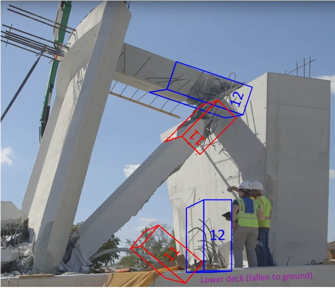
and

[and added later, from the link epoxybot posted 17 Mar 18 04:22.]
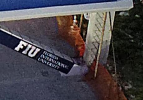
Now side view of deck at 11-12 after collapse:
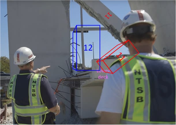
... and finally, a closer look at the connection point where 12 and 11 are no longer connected to the deck.
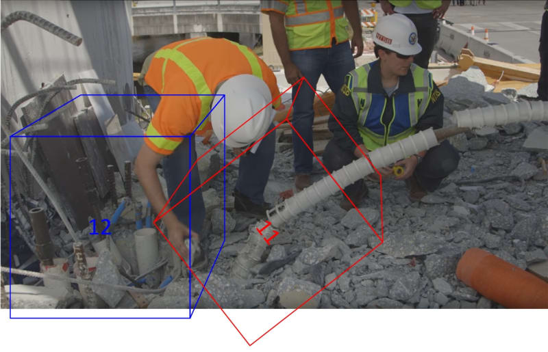
One thing that strikes me is the likely difficulty of transmitting compression from 11 to the deck right in front of the openings for all the services in the vertical 12. And where's the rebar that would tie member 11 to the deck? Perhaps obscured by the rubble, and/or torn out and still attached to #11. But maybe engineers who actually know something about this topic would see something different.
The last two images are from the NTSB videos, linked in my previous post.

and

[and added later, from the link epoxybot posted 17 Mar 18 04:22.]

Now side view of deck at 11-12 after collapse:

... and finally, a closer look at the connection point where 12 and 11 are no longer connected to the deck.

One thing that strikes me is the likely difficulty of transmitting compression from 11 to the deck right in front of the openings for all the services in the vertical 12. And where's the rebar that would tie member 11 to the deck? Perhaps obscured by the rubble, and/or torn out and still attached to #11. But maybe engineers who actually know something about this topic would see something different.
The last two images are from the NTSB videos, linked in my previous post.
Looks like someone is clamming up, From Fox News:
“The city attorney is advising us not to speak about anything to do with the bridge,” said Sandra Antonio, a spokeswoman for the city of Sweetwater,
...National Transportation Safety Board had forbidden engineers or contractors from talking about the project pending its investigation.
A FIGG spokeswoman, Cheryl Stopnick, said it would be “inappropriate to discuss specific detail about bridge design” during the investigation.
A spokeswoman for FIU did not immediately respond Tuesday to questions about the pylon relocation in the bridge design.
Happy as a clam...
Dik
-
1
- #45
According to the page 115 (Drawing sheet B17, 2015 NOT FOR CONSTRUCTION DRAWINGS), there is no PT rods in #11. But reality doesn't seem to fit those drawings.
Those drawings are hardly rough sketches either. There are quite specifica about the placement and loads of the PT rods including orientation within the beams so they don't interfere with each other at the nodes. (AKA some PT bars in cross section are in the XZ center plane, others in the YZ centre plane while are distributed to the corners.) One would suspect that member #11 wouldn't need PT once the bridge is in place as there is already significant compression. Adequate nodal reinforcing however would be obviously essential. If however adequate nodal reinforcing isn't present then tensioned PT rods could help keep the connection together.
That said it would seem the PT tendons that did exist in #11 were essential to holding it together. If we make the reasonable assumption that the PT adjustments that were being made was the straw that broke the bridges back.
As mentioned about this likely allowed the connect.on that was already under significant strain to shear. One would expect that adequate reinforcement would have been provided for. But clearly it wasn't.AUCE98 said:I worked for VSL as an engineer for two years several years ago, mostly monostrand commercial building design work. My understanding from some former coworkers was that they were in the process of de-stressing one of the threaded bars when it collapsed. So they were attempting to reverse the stresses within the no. 11 diagonal when the collapse occurred.
-
1
- #46
Tomfh said:Does anyone know the size and load of those two PT rods in #11?
From Ingenuity's post, "Keep in mind that the 1-3/4" grade 150 ksi bar was stressed to 280 kips (max), about 70% of UTS."
-
1
- #47
Here's a picture, for what it's worth:Tomfh said:Does anyone know the size and load of those two PT rods in #11?
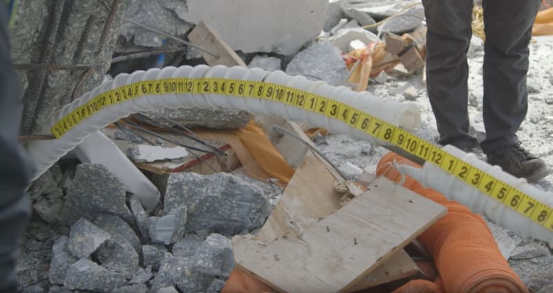
From: I believe that yellow tape is either 1.25" or 1.5" wide.
PE2015, in your
I see strain transducers on most members, a couple at bottom blisters and other sensors along the deck, with red wires connecting to a data-logger.
They were monitoring the structure and logging strain and more during the move.
Appear to be ST350 Strain Transducers
I see strain transducers on most members, a couple at bottom blisters and other sensors along the deck, with red wires connecting to a data-logger.
They were monitoring the structure and logging strain and more during the move.
Appear to be ST350 Strain Transducers
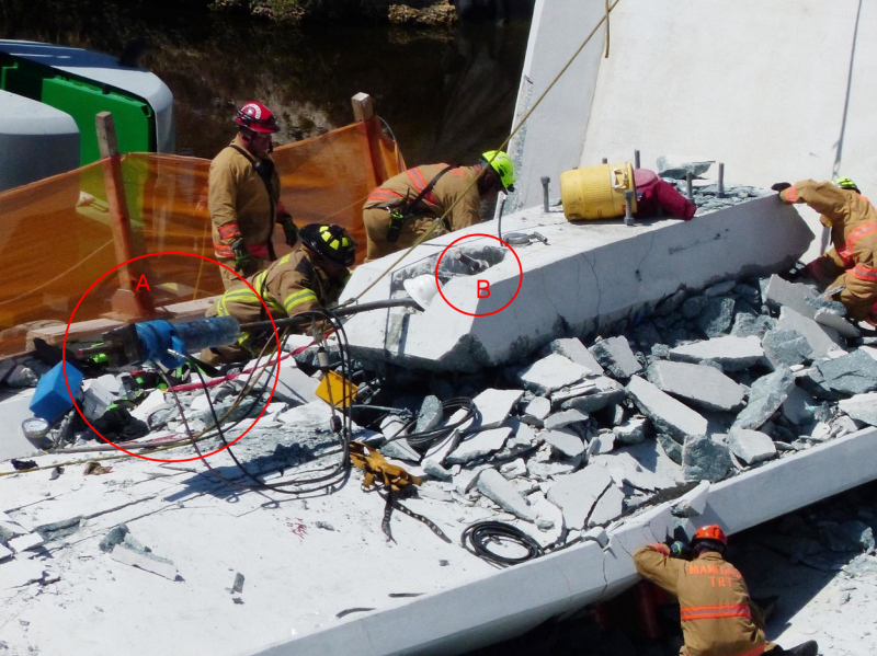
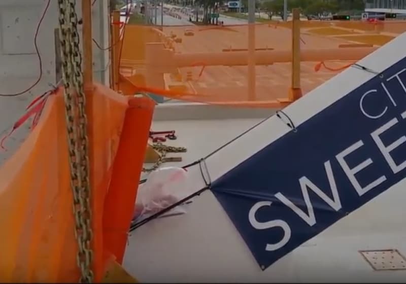
And from Stuart Grant's Another view of the 11-12-deck connection. Unfortunately can't quite see how 11 relates to the deck.

Oh dear. Anything for limelight, even if you are an idiot with a 'Dr.' in front of your name.hokie66 said:JAE,
That Oliver McGee character was on TV news, espousing that rubbish. I linked it in the first thread. He is some sort of professor at Texas Tech. He needs stopping.
There is a whole bunch of 'amateur' conjecturing and speculation going on in this thread but at least there is virtually instantaneous peer review. Plenty of new sign ups to this forum too (myself included) so who knows what credibility so many of these posts have. But that is the nature of community discussion and in the right contexts good conclusions can emerge.
In contrast Oliver McGee is an idiot, who reporters have no idea that they should ignore.
You would hope they do have excellent forensic engineers examining this. Some silence from them is understandable, however complete silence just allows airtime for idiots.
-
2
- #52
Again looking for views of the 11-12-deck connection.
From
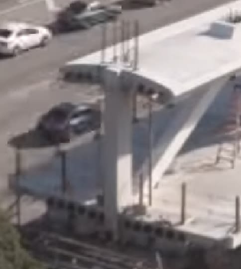
And from
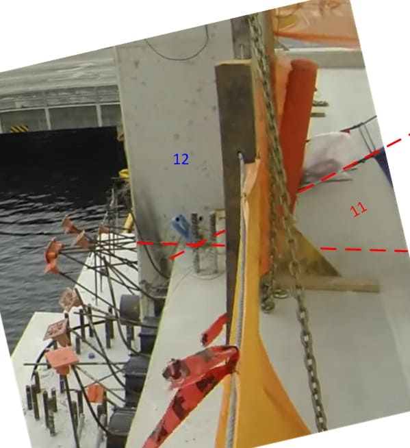
[Revised: added diagonal dashed line so that red line intersections indicate better position of 11 relative to deck and 12.]
From

And from

[Revised: added diagonal dashed line so that red line intersections indicate better position of 11 relative to deck and 12.]
human909 said:That said it would seem the PT tendons that did exist in #11 were essential to holding it together.
Yes that's what I was thinking. Maybe the PT was acting like anti-burst. Not strictly needed for the member, but helped keep everything bandaged up tight.
-
1
- #54
This discussion has slowed a lot, and with all the guessing we have done, I don't think we know exactly where the failure initiated. Perhaps we never will.
Someone, I forget who, suggested that it would have been easy to conduct a load test in place before the precast bridge was moved. True, just support it a bit off the ground and load it with sand bags or water bladders. Plenty of sand and water in Florida. I suspect it would have failed the load test, and thus the lives would have been saved. We will never know now.
For what it is worth, it is my belief that we do not have the tools available to analyze this structure adequately. The engineers at Figg must have thought differently, but that may have been because their many successes with different bridge types made them overconfident, or perhaps it was just arrogance.
12345abc6ttyui67
Structural
Zero experience with bridges, or concrete, or pre/post tensioning, but also rolling around in my head is the arrangement of the PT strands at the top of member 11. If we believe the not for construction drawings we've seen, one strand goes right through to the top of the blister, past member 10, whereas the other stops short and is embedded in the joint, before member 10.
They were presumably working on the 'longer' PT strand as that lines up with where the construction guys were on top of the bridge before collapse. It doesn't make much sense that releasing compression from the strand would cause failure when the member is acting in compression anyways - technically you should be making the situation better (less compressive stress).
What I am wondering is what else besides applying compression was that 'long' PT strand doing? It looks a lot like any compressive loads in that strand would also help to carry shear between the top ends of members 10 & 11 and the canopy. By releasing the compression in the strand, has more shear load (unsuccessfully) been transferred through the remaining members of the joint?
EDIT. This is the picture to which I refer (from Pt 1 of this thread). If you picture this drawing without the 'long' strand in member 11 (e.g. if compression had been removed from it) the joint as a whole looks awfully weak to me with very poor load paths between all of the members.
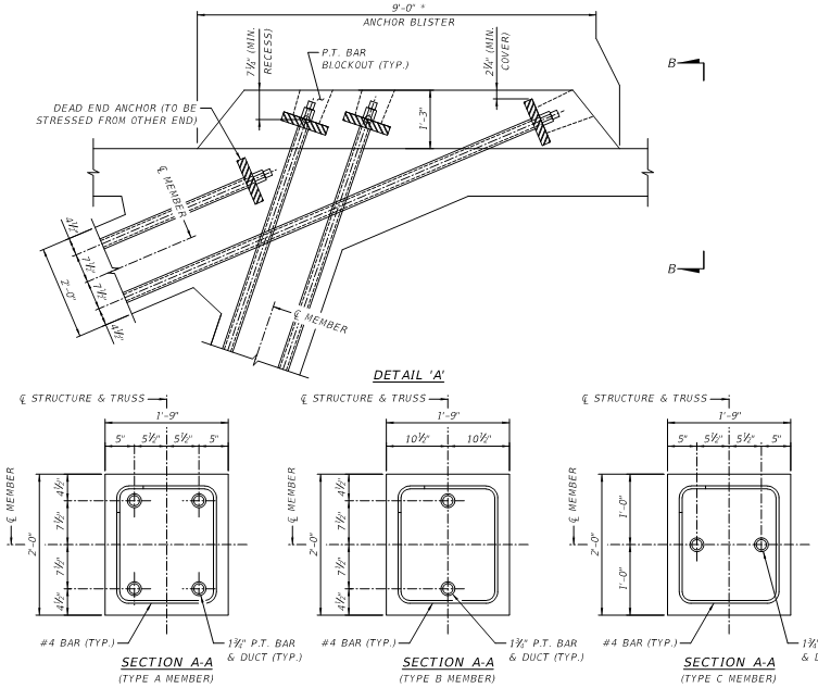

12345abc6ttyui67
Structural
gwideman - I thought B was one of the strands of member 10? Maybe I am mistaken.
Im a chemical engineer, so to those who know about this subject:

This shows a drawing of the pedestrian bridge when finished from my local (Danish) engineering society paper. Why was the bridge erected without the cable stays? Wouldnt a bridge like this normally be build so that the pylon was build before the span is installed? Was this a part of the "accelerated bridge construction"? Or is the drawing an outdated drawing?
Best regards, Morten
LittleInch
Petroleum
I think hokie66 has nailed it. Every time I see the videos of this collapse I am astonished by the speed of collapse. This thing just broke in two at what seems to be two or three locations within a fraction of a second of each other. Without super high speed filming I'm not sure you will be able to say with any real certainty which element broke first or which was just the subsequent rolling damage. Hopefully some of the testimony of the survivors from the top of the deck doing the work will be able to shed some light.
Someone may be able to show after many days/months of analysis that some element was not properly designed or constructed, but from what I've seen and read here, there were a number of elements which could contribute to the failure and that the analysis tools for such a structure were maybe not fully developed.
The changes to the design (11 ft longer) and subsequent change to the lifting points may be the smoking gun as everyone would be reluctant to go right back to the start design again. Hopefully this will go to show that with newer designs and construction principles you need to test the thing in a safe location before allowing people to drive underneath it or work on top of it.
Remember - More details = better answers
Also: If you get a response it's polite to respond to it.
- Status
- Not open for further replies.
Similar threads
- Question
- Replies
- 27
- Views
- 28K
- Replies
- 1
- Views
- 5K
- Replies
- 13
- Views
- 13K
- Replies
- 6
- Views
- 3K
- Replies
- 17
- Views
- 11K

