Eng-Tips is the largest engineering community on the Internet

Intelligent Work Forums for Engineering Professionals

Miami Pedestrian Bridge, Part III 99

Status
Not open for further replies.

JStephen

Mechanical
Aug 25, 2004
8,602
0
36
US
"Site management has requested that we limit the length of the other thread by forming a new one. This subject may require III, IV...."
So here's Part III. Please don't post any more in Parts 1 and 2.

Part I thread815-436595
Part II thread815-436699
 
Replies continue below

Recommended for you

winelandv said:
Some 400 engineers trying to design something via forum? It would certainly be entertaining to watch. :)

When we built my parents cottage/homme, my dad, my brother, and myself all knew how to build things... but, put three people together to do it... we eventually divided up the chores and identified the work we would undertake... can't imagine 400...

Dik
 
"... can't imagine 400..."

Famously, it took about 400,000 people to put a man on the Moon before the decade was out. A bit of a Project Management triumph, as much as the other disciplines.

 
In a post near the end of thread II I mentioned the appearance of something moving spanward from the position of column 12. Further review estabilishes that as a structure in the far background coming into view from behind the column and the crane boom in front of it (dashcam view). Just wanted to correct that. The other points I made there hold up a little better.

Studying the drawings and the readily available pre- and post-incident imagery of the 11/12/bottom chord/pedestal area I note that the remaining portion of 12 seems to have a "chair" shape, the outside surface extends to somewhere above the location of the drain pipe while the spanward face ends higher, around deck level, and there seems to be a roughly rectilinear transition between the two cleavage planes.

The drawings show the PT in the lower chord equally spaced (though of graded sizes) and straddling the "core" area of the deck, where the diagonal members sheer interfaces are. In both the independent span design and the complete bridge design I do not see how the compression force is to be transferred to the PT cables.

Two other things about this design bother me. It's clear that the mast that was to support the false stays was to be supported by a foundation built in place around member 12 of the independent span and the matching vertical member of the north span. The false stays would provide, if adjusted reasonably well, ample guy forces for the mast in the axial direction. But what was to counteract the torque around the base of the mast in the transverse plane? I'm not seeing that in the design either. If it's just cantilevered it seems to me there's a lot of complex moments operating on a complex multi-pour and seemingly narrow column. The proposal package only mentions the construction of the mast briefly, showing it as having two cast-in-place components, sheet B-28. The art showing views along the deck illustrate the "base" part of the mast ("cast pylon") as being only a little wider than the diagonals and the plan view shows no bulging of the deck to allow foot traffic to flow around a wider base. All of while leaves me wondering about the moments in that area in a stiff breeze.

And the design of the drain. Apparently the desire to avoid cosmetic issues or wastewater handling costs at the center pylon led to a design in which all the water collected by the deck was to drain through the central pylon bearing area and then the south abutment. The drain pipe was external to the deck structure mid-span but passed through the end flanges and was partially recessed in a "groove" cast into the bottom of the chord. It seems to me that the groove for that drain pipe would create stress concentrations, my reflexes want to see a much bigger radius there and rebel against the complexity of passing the 8" drain line right through the center of the mast foundation.


"In order to reduce tension on a PT strand, tension must first be added- the jack and stool are attached and the tendon is stretched so that the nut on one end can be loosened by hand. So, for a short period, the PT strand being loosened is under significantly more tension, and is applying significantly more load to the member, than the designed installed load. If there's a mistake during the procedure for reducing strand tension, the tendon could fail or the member could be grossly over stressed."

As I stated in my original post on Part II. Member 11 was originally in tension during transport since the bridge transport trolley was below the first interior panel point when the bridge was being moved. When the bridge was set in place the stress in member 11 was reversed. In my opinion the proper procedure would have been to de-stress the tendons while the trolley was still supporting most of the weight of the bridge. In other words the bridge end was in full contact with the pier but most of the load was still being supported by the trolley. Whether this method was assumed by the designer but not properly communicated to those in the field is not known at this point but it will eventually come to light.
As jgKRI stated above the strands have to be stretched so the wedges can be removed. The fact that there was full dead load on member 11 plus a prestress force that was probably not considered in the design plus an additional force due to the detensioning operation is significant and is probably what caused the failure.
Whether it was a compression failure at the end of 11 or a shear failure for load transfer between 11 & 10 cannot be determined with out construction documents because both the cross sectional area and reinforcing are needed to determine the stresses on each member at the time of failure. With shear strength being significant less than compressive strength for concrete, the shear would be the first thing I checked. It is also not known what the compressive strength of the concrete was the time of the accident. If the concrete was at only 75% of design strength that would be a critical factor.
 
A lot of interesting discussions and seemingly good information going thru these three threads.

I have feeling what may come of this at the end of the day is everyone performed their work to the standard of care. Perhaps at or near the member 11 top node the concrete never achieved strength or possibly had poor consolidation around the PT bar anchorage zone which predicated a punching style failure during the temporary jacking operation to destress the bar coupling this with the apparent lack of redundancy could have lead to sudden and catastrophic failure of the "Truss".

Personal opinion with no basis other than the limited marketing material and photos presented so far.

Edit: based on photo below, I revised my failed node assumption to be at the top not bottom of member 11.

Open Source Structural Applications:
 
Stephen Nuchia (Electrical) said:
... I note that the remaining portion of 12 seems to have a "chair" shape, the outside surface extends to somewhere above the location of the drain pipe while the spanward face ends higher, around deck level, and there seems to be a roughly rectilinear transition between the two cleavage planes. ...
On collapse, members #12 base was knock out by member #11 and pulled down from pylon together with member #11, by north deck fall.
That can explain the "chair" shape after collapse.
 
For the time being I'll put aside the question raised earlier about whether this structure would behave like a beam or a truss, and for current discussion assume this acts like a truss. Not a normal truss, however, but a frame with fixed nodes. And this would be a complex frame, with internally applied moments from the external PT.

When modelling, the designer should have accounted for moments to develop at all joints. If they didn't, that's a problem. For a proper review it's necessary to see how the designer modeled the structure in their finite element model (they surely must have done this in order to capture the behavior of this complex little frame). As mentioned earlier in this thread, the axial dead load stress just from compression in member 11 is already high, and was the first thing that caught my eye when I looked at the bridge. Now add to this some undetermined moment load, and flexural stresses could become critical. Then also combine this with the fact that minimal shear reinforcement seems to exist in member 11, and things could become dire (this lack of significant observable shear reinforcement in pictures has also been mentioned before).

And just to note the obvious, the load path to the bearing is thru member 11. It's axial stiffness is much greater than the flexural stiffness of the top chord above it, and as such 11 will attract the load.

Having said all that, the following is a hypothetical collapse sequence based on concerns with design of member 11. To date, I've seen nothing in the limited, grainy, heartbreaking video to contradict this proposed sequence of events.

1) First member to fail - member 11:

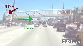
Diagonal, under high axial and shear loads, becomes critical with the additon of moments at member ends [This may or may not be connected to the external PT that has been so much talked about. Destressing of the PT rod, however, as some speculate was the operation being performed at the time of collapse, would actually reduce shear capacity of section]. The integrity of the end(s) become compromised, pins develop as a behavior mode, with final result being brittle shear failure at one, or both, ends. Note that from pictures it does not appear that the diagonal buckled, as the center zone of member appears to be relatively intact. Also, the "zippering" along the bottom side of 11 is likely the result of PT bar being ripped out during collapse.

2) Second member to fail - top chord/flange above member 11:
After member 11 fails the structure is "theoretically" still viable, assuming we have frame behavior. However, this is obviously not sound. So next, the top chord near intersection with 11 fails quickly in shear and flexure; top chord is much weaker than bottom so top fails first. It's also possible then that the longitudinal PT force in the top chord, combined with the instantaneous frame bending of structure in this corner, causes 12 to fail in bending at its base in the diaphragm area. And it's even conceivable that member 11 becomes "detached" from the bottom slab and is driven along the top surface of the slab, impacting 12 and causing additional damage to its base. This could explain why the final resting place of 11 & 12 are on top of the pier.

3) Bridge collapse:
After top chord fails the only section remaining is the bottom slab. Location where loads are highest is where the bottom slab intersects the next diagonal 10. Bridge now hinges at this point and falls. At some point during fall the longitudinal PT force in bottom slab pulls this now free bottom chord (section beneath 10 & 11) off its bearings, and that entire end of bridge plunges to ground. Punching out of anchorage blocks on top is likely the result of impact of falling bridge.

>>>
An alternate, albeit unlikely, failure mechanism:
With diagonal member 11 carrying all dead load back to bearings, the zone of shear transfer at the intersection with member 12 and the bottom slab is crucial. The load is entering the bottom slab, and all that wonderful longitudinal PT spread out across the entire cross-section, at a single point--midspan. Adequate shear and confinement reinforcement must be provided to ensure that the horizontal component of load from 11 can be distributed back into the slab. If not, triangular frame of 11-12-top chord could conceivably pop out of end diaphragm in a prying action-like behavior, leading to catastrophic collapse. The video, however, doesn't appear to show this, although that could be merely a trick of the eye. And there's also the fact that 12 appears to have failed in flexure at its base, ABOVE the surface of the deck.
 
The terminology is important, so please use 'chord', not 'cord'.

I have stopped speculating about where it failed first, but we should not be focusing only on the prestress. As this was concrete, other factors are involved. Shrinkage, creep, etc. We don't know how this was cast, but there must have been construction joints. At these joints, the later cast element is restrained by the earlier elements. The prestress was presumably applied only after the whole thing was cast and hardened, so there would have been some cracking already.

I don't think there will be a call for any more concrete truss bridges in the near future.
 
This can be between 1) and 2) as south structure/frames from member #11 was still working as one.
FiuBrRot_g58kqw.png
 
LittleInch said:
Hopefully some of the testimony of the survivors from the top of the deck doing the work will be able to shed some light.

Firstly god rest the soul who died on the top deck as it fell, and same to all the other victims.

As for the other top deck survivors, the speed that thing went, they won't have has time to sh1t themselves let alone consider the reason they were falling.

I'm also starting to think about the other blameless victims that this event will affect. This must be an extinction level event for MCM & FIGG. Might be tricky time for anyone with those names on their resumes for a while. I truly hope that justice prevails and the genuinely culpable individuals are held to account and more importantly the lessons learnt for future.

 
gwideman's summary above, I believe, likely captures what happened. As the diagonal member 11 pushes in compression, the bottom slab has to tore away from 11 and 12 first in order for a significant deflection to occur. Since a large portion of the bottom deck is still resting on the pylon, it did not fell down immediately until the deflection is large enough.

A large deflection would not occur if (1)the bottom slab would not tore away from 11 or (2) diagonal 11 buckling in compression.

The top deck between 12 and 11 is not doing really much.
 
Hokie66,

Hear, hear! All the minutiae about which member failed and how, while ultimately valuable, rather sidesteps the issue: this was a horrible design.

It was designed to be an expensive taxpayer-subsidize landmark. Actually functioning as a pedestrian bridge seems to be a secondary concern. Had they wanted the later it could have been had at probably a quarter of the price and built using a (boring) proven, less risky design. Pride goeth before a fall.
 
Archie264 said:
Hear, hear! All the minutiae about which member failed and how, while ultimately valuable, rather sidesteps the issue: this was a horrible design.

I don't think that is in dispute. But what is the point discussing the obvious. Hence the discussion about more specific aspects. In the absence of great information there is always going to be speculation alongside analysis.
 
A new statement from NTSB: "The investigative team has confirmed that workers were adjusting tension on the two tensioning rods located in the diagonal member at the north end of the span when the bridge collapsed. They had done this same work earlier at the south end, moved to the north side, and had adjusted one rod. They were working on the second rod when the span failed and collapsed. The roadway was not closed while this work was being performed."
 
It looks like they have needed to do some chipping around the PT Blister opening. Having a hammer chisel strike the plate washer of the PT strand would account for the strange whipping sound one witness remarked on. It would have somewhat of a warped echo sound.
Hammer1_ottyby.jpg


Bigger:
 
Ron said:
This is exactly why an engineering firm should NEVER be a subconsultant to a contractor in design-build.

Design & construct projects are completed successfully every day of the week. Design-only/construct-only projects can and have had the same problems with even larger numbers of fatalities. You think end-clients don't have the same budget and programme pressures and don't project those onto their design-only consultants?
 
Status
Not open for further replies.
Back
Top