Eng-Tips is the largest engineering community on the Internet

Intelligent Work Forums for Engineering Professionals

  • Congratulations waross on being selected by the Tek-Tips community for having the most helpful posts in the forums last week. Way to Go!

Miami Pedestrian Bridge, Part IV 74

Status
Not open for further replies.

Most opinions are agreed on member 11 to be problematic.

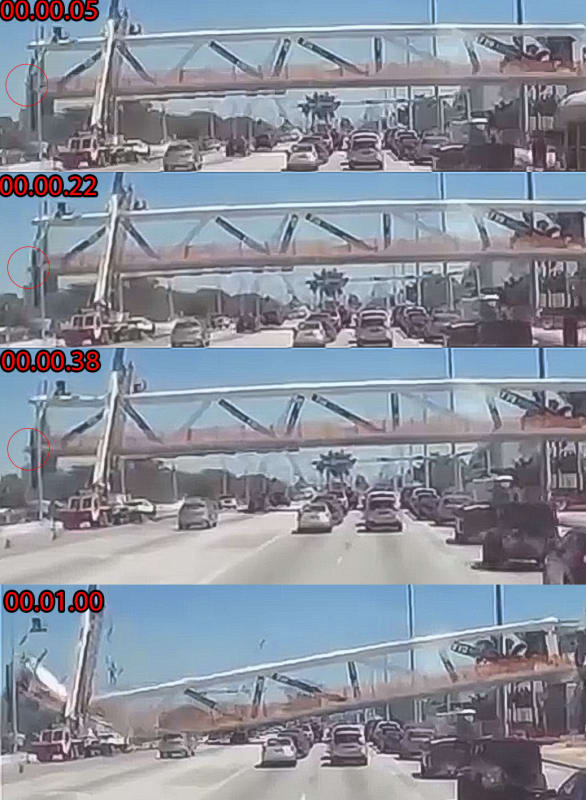
The evidence in front of our eyes are the canopy (upper deck and top chord of the truss) and the walkway (lower deck and bottom chord of the truss) are still reasonable intact and in one piece. Some truss members could not be seen in the north half and some appear to have punch through the roof.

The important Member 11 actually is still intact and lied behind the folded canopy with the broke off end pointing upward after it has pulled/sheared off from the walkway which is resting on the ground. The PT duct has come off by breaking free all the stirrups (shear reinforcement).

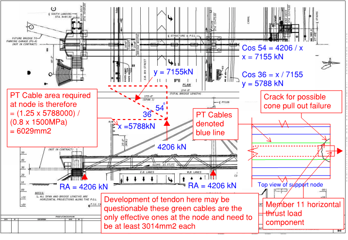
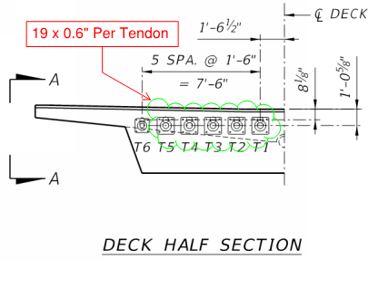
The design drawing shows the walkway has been post-tension both longitudinally with 12 PT ducts and transversely with PT at 2' 6" centers. That explains it is still in one piece lying on the ground.

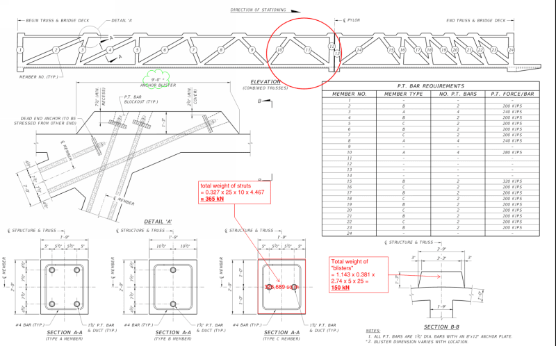
Thus the joint of member 11 has broken from the walkway which is 31ft wide acting as the bottom chord for a truss of only approximately 2ft wide. The first question to any designer is how much width of the walkway can successfully interact effectively with the middle truss. There are guidance in the codes for that.

Some serious reinforcement would be required to dissipate the force in the member 11 into the bottom and top chords of the truss?

The broken concrete of member 11 in the photos show only a few small diameter bars.

If the structure has been analyzed as a rigid frame, which I cannot see any other alternative, it is the designer's duty to make the joint rigid enough to transmit the shear forces and bending moments.

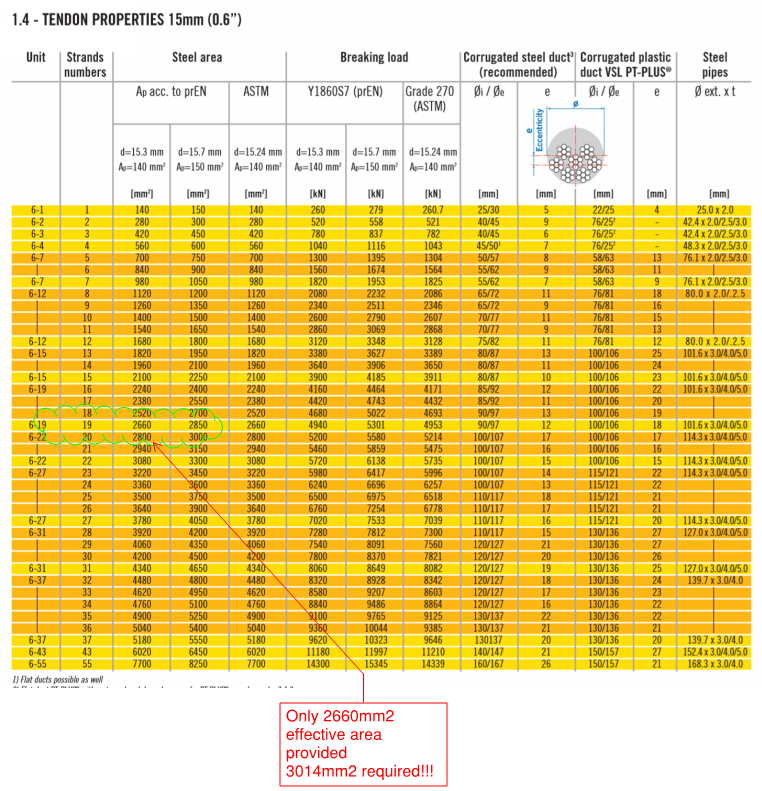
Due to the changes of transporter positions Member 11 was in tension due to one bay free hanging like a cantilever. It is possible that the designer mitigated this change by adding PT ducts, which were not listed in the original design drawings. When the bridge was supported finally on the two end abutments the axial force in Member 11 changed to compression so it would have been a need to adjust the bolts by tightening it.

The member 12 and its connected top chord canopy are redundant as the structure without them can still work like a standard Warren truss. The joint in the bottom of member 11 must be adequately restrained or it can shear outward to trigger a failure. The photos, provided by gwideman on earlier post on 21 Mar 18 04:50, of the fully exposed bottom end of Member 11 does not show evidence that the joint there has been adequately reinforced to dissipate the force, shear and bending.

It is possible that Member 11 and 12 became detached from the walkway during the collapse but the same photos show the top of Member 11 still attached to the top chord or canopy which has a much more robust joint arrangement. However the canopy folded just before the robust joint section.

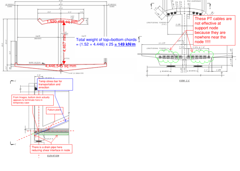
The broken-off end of Member 11 has rebar I estimate mostly small diameters like 5/8" to 3/4" and does contain any transverse PT duct or tendon. The densely spaced 67 number of transverse PT casing has a concrete cover of 3.75". This could suggest the Member 11 could have shear off outward to the North with a layer of maximum 3.75" of the top concrete from the walkway. The downstand beam here is also only 2'10.5" wide. The south side, with a 3'6" downstand beam did not collapse and still have the canopy and walkway separated by middle truss after the collapse.

There is no code to help a designer on how much steel reinforcement to put in to dissipate the stress. It is down to experience and to realize the design assumption that the joints are rigid enough. When the reinforcement drawings are available a more definitive assessment could then be made.

The evidence so far points to the Member 11 wasn't adequately reinforced/connected to the 2'10.5" wide downstand beam and the walkway. May be the embedded longitudinal PT anchors were in the way but the designer must have a scheme to pass the axial tension (occurred during swingin-in) and then compression (in service) into the walkway because the truss system lies in the middle empty 3'1" corridor where there is no longitudinal PT system.
 
Cold joints are inevitable. And you would not want to cast the inclined members with the canopy, as plastic settlement could result in a gap at the top of the web members. So sequence of placing concrete was correct. It was the design which was deficient.
 
From the photos above by Meerkat 007 and JRS87, damage to 12 base appears to extend nearly to mid-height! And in the "end on shot" of 12 there's a stub that extends from the base that is almost semicircular, as if the front side was pummeled, causing the weaker corner edges to be chipped away. It's hard for me to see how this could happen if the 11-12 base sheared off together as a unit at the construction joint/ deck surface.
 
TheGreenLama - on the III discussion board, 4Alfie.Tx posted a simulation that suggested that the 11-12 base indeed did not stay together, else member 12 would have been pushed to the north. Quote is below

"Meerkat007, your comparison between bridge collapse movie and theoretical simulation of truss without member #11 looks similar. It tells that the diagonal #11 crumbles at the base first, otherwise, it would have pushed out #12 a great distance based on the geometry as shown below, before the base slab tore away from #11 and #12."
 
Meerkat007 and jrs87 photos show the steel reinforcement of the broke-off end of Member 11 still firmly attached to Member 12. However no significant reinforcement is visible between these two members with the walkway which is supposed to work as the bottom chord of the truss.

The left-over of the Member 12, which is still on top of the pier, is a strong evidence the Member 12 have detached from the walkway by a horizontal force overcoming the shear capacity of the connection.

Meerkat007 has identified the bulge in the 17/19 seconds of the Zac Doyle Youtube video. This collaborates rather well with gwideman's shear failure sketch posted 23 Mar 18 17:09. When considering the positions of the longitudinal and transverse PT systems and comparing them with the photos it is possible the shear plane might have occurred at a slightly higher lever.
 
Regarding the concrete pour sequence.

1. I think the Miami Herald video referred to by appster is actually a computer animation, and may not reflect actual steel or actual concrete sequence. Correct me if I'm wrong.

2. What do we actually know about what was poured when? In the Stuart Grant video linked by rebardan, concrete trucks show up at about 1:33, and next day, or following day, forms are stripped and deck and vertical and diagonal members appear to be done, so that would mean the deck and the joints at the deck were poured more or less continuously. But I'm not really sure what I'm looking at in the video, nor whether the time lapse has had "non activity" edited out.
 
Does anybody know what tendons were specified for the bottom chord of the truss? They are type 5 specified on the drawings (meaning each cable is 13mm dia.) however it doesnt specify how many cables per tendon there are.

** Edit, I have updated the check below to show the 0.6" x 19 cables per tendon which was found in earlier thread and brought to my attention by username Ingenuity this is numerical proof now of where the failure is and why it failed**

***Case Closed***

Bridge_Summary_1_azfyxt.png

Bridge_Summary_2_rsuiuh.png

Bridge_Summary_3_apqqqj.png

Bridge_Summary_4a_xgxh1g.png

Bridge_Summary_4_kdvdog.png
 
gwideman - what is happening between 1:24 and 1:25? I thought that could be the deck pour but I also am not really sure what I'm looking at.
 
Sorry, not sure if I was clear on my previous post, my hypothesis is as follows:

- Insufficient development of bottom chord reinforcement at the node of member 11 and 12 junction.

- This is further made worse by the drain pipe punching through this junction as well as grout ducts/tubes either side of member 12 at this node. This reduces the shear plane area and makes it harder to engage the PT tendons that are quite some distance away from the node itself.

- The node detail is made even worse by the fact that the end face of the bottom deck doesn’t actually continue all the way to the outside face of member 12, making development of the PT cables where it is required even more problematic. This means we are engaging very few of the cables in reality at the node.

I’ve completed a few rough hand calculations to verify the loading and forces we are dealing with. I am old school and believe that we don’t need FEA or fancy analysis to solve such a simple determinate system.

My biggest surprise is the media didnt overfblow the bridge weight to make the story more interesting, the bridge does in-fact apear to be circa 900-990 tonne of self weight.


Timed the collapse, took a little under half a second from the first suspicious event before the structure visibly bends. The first frame is where I was able to pick up a batch of pixels that resembled the concrete protruding from the bridge. The debris seems to blow out at least 5-6 feet at the 1/3 second mark before the bridge comes down.
STOP_WATCH_k2ulri.jpg
 
SheerForceEng said:
Does anybody know what tendons were specified for the bottom chord of the truss? They are type 5 specified on the drawings (meaning each cable is 13mm dia.) however it doesnt specify how many cables per tendon there are.

Yes, the PT has been summarized in previous parts. See thread815-436595 and go to post with time:date stamp of 17 Mar 18 07:27
 
ingenuity said:
Yes, the PT has been summarized in previous parts. See thread815-436595: Miami Pedestrian Bridge, Part I and go to post with time:date stamp of 17 Mar 18 07:27

Thanks for this, I have updated above, it shows it pretty conclusively now.

I have used some data from this forum as well to help with the numbers so thanks to everyone for contributing.

Cheers,
 
saikee119 said:
Meerkat007 and jrs87 photos show the steel reinforcement of the broke-off end of Member 11 still firmly attached to Member 12. However no significant reinforcement is visible between these two members with the walkway which is supposed to work as the bottom chord of the truss.

I see the reinforcement of 11 as entwined with 12, not firmly attached, and it is entwined higher up 12 than its original location.

And in the 4 screen grabs by INCENTIVE immediately above, member 12 looks to remain in the vertical position for the first 3, well after the postulated debris is blown out of the end.

And in one of the earliest posted videos by Tomfh in Thread I, 18 Mar 2:42, member 12 actually looks, of all things, to be pulled inwards. Of course its final resting place is on top of the pier, so 11 would have to push it out in the final moments.
 
Previous posts in PART I, II and III of this subject have asked about previous prestressed concrete truss bridges.

I was recently browsing through a book "200 Years of Concrete In Australia" and came across this construction photo of the RIP Bridge (no it is not an acronym of R.I.P). It is a prestressed concrete truss, located on the waters of Woy Woy, about 100 km north of Sydney. Constructed in 1974. Main center span of 183 m (600 ft) and a total length of 330 m (1080 ft):

Capture_RIP_BRIDGE_1_zhwwfj.png


If I recall correctly, it "suffers" from excessive upward deflections at the center. During the period of when free cantilever bridge construction was in its infancy, several bridges experienced excessive creep deflection, with noticeable mid span sag (downwards displacement), so additional prestress was applied to avoid any sag - unfortunately too much prestress was applied to the RIP Bridge, and 'creep' - acting opposite to gravity effects - caused its midspan 'hump'.
 
SheerForceEng
As I pointed out in Part II shear lag is a definite design consideration in this structure particularly at each end. The ducts in the deck are plastic even though I feel they should be metal to make the bond more secure for the grouted strands; there is no lateral distribution reinforcing of any consequence near the strand terminations and the lateral deck tendons are at 2'-6" oc. If your theory is correct then the structure should have failed at the opposite end where member 2 is at an even flatter slope. Are there fewer service ducts and post tensioning ducts at the other end reducing the effective bond and local area of concrete.

Not sure but lateral distribution of loads from the web to the flanges is definitely an issue and could be a factor in the failure. As per Ingenuity I would not cash the cheque yet, case to me is still open.
 
appster said:
If your theory is correct then the structure should have failed at the opposite end where member 2 is at an even flatter slop

Because the trigger is destressing the temp PT bars in member 11 If destressing didnt occur at the other end yet then it will still have the PT tension bar artificially holding the node together.

ingenuity said:
Aussie sarcasm - dies hard!

I get it mate Im Aussie!!!!!
 
They announced that de-tensioning had been completed at the other end and one rod on the North; were working on the last bar when the failure occurred.
 
Re: SheerForceEng (Structural)24 Mar 18 01:32

Very good post, I agree. As to FEA, I would not be surprised if NTSB builds a physical copy of 12-11-deck portion in their lab.

The the end-on photo of 12, I see a faint sign of a large perpendicular bore hole in fracture.

Does anyone know what deck rested on? In photos I see what appears to be 4 nylon bearings at top of pylon pier. Are these spaced in such a way 11 can punch through deck? I don't know.
 
INCENTIVE said:
(Dashcam frame-by-frame)
Off the left end I see a few pixels of something. More conspicuously, I see a more solid object progressively protruding to the left at deck level, which it's tempting to see as 11-12 pushing out to the left, maximum at 00.00.38. However, it could also just be that "protrusion" is really just the north-west corner of the deck and changing perspective as the vehicle and camera move toward the bridge. Someone on an earlier part of this thread discussed this too, I don't recall the conclusion. Unfortunately that area is behind what I believe is a cherry picker arm, so difficult to see the continuous visual lines of the deck.
 
Status
Not open for further replies.
Back
Top