Continue to Site

Eng-Tips is the largest engineering community on the Internet

Intelligent Work Forums for Engineering Professionals

  • Congratulations GregLocock on being selected by the Eng-Tips community for having the most helpful posts in the forums last week. Way to Go!

Miami Pedestrian Bridge, Part IV 74

Status
Not open for further replies.
From the dashcam video, it appears the main deck failed first, at a point midway between the two verticals. Not at the 11-12 beams themselves, nor at the node where they intersected. The outboard (short section) then tilted (pivoted) down to the roadway with its nodes intact, but the rest of the bridge deck than fell nearly straight down.

As an aside, it is still not clear how the designers intended to drain that "bathtub" in the top of the cover. The center is high, so separate independent drains would be needed on both sides, but out there even white plastic pipes would be eyesores on this "architectural wonder" ...
 
racookpe:
I have been looking closely at the various photos and somewhat agree with you.
Consider:
Did member 11 fail due to crushing near the connection with member 11.
A crush failure would allow the member to effectively shorten and lead to the failure of the deck.
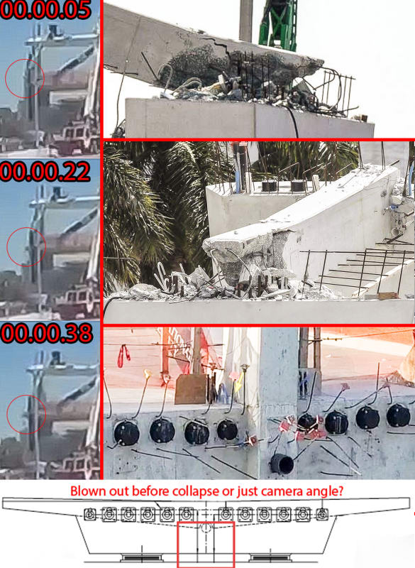
A crush of a portion of member 11 may account for the burst of dust seen behind member 12 immediately prior to the collapse.
Although the end of member 11 may have crumbled, effectively shortening it, it may have retained enough length and strength to hold the bottom of member 12 on top of the support as the main deck fell.
The damage to the bottom of member 12 may be consistent with the main deck falling away and breaking free from the support.
The rebar from member 11 and member 12 look to be running to the top of the support.
Once the 11-12 connection broke away from the main deck there is little save gravity to hold them on top of the support.
The damage may be consistent with the top of member 12 being restrained by the top canopy and the bottom of member 12 being restrained by the remnant of member 11 as the main deck fell and rotated away.
Note also that the end of the PT rod embedded in member 11 is still attached to the deck.
If the broken end of member 11 was supported by the support column and rebar connecting member 12 while the deck fell away with the end of the PT rod still attached, that would explain the PT rod "zippering" out of member 11.
Surely the connection between members 11 and 12 and the deck was much stronger than the connection between the 11-12 connection and the deck.
If the deck rotated away while the bottom of member 12 was somewhat supported by the remnant of member 11 the damage and final position of the various members may be explained.

Bill
--------------------
"Why not the best?"
Jimmy Carter
 
Alternately; The pinging noise reported may have been a failure of a PT tendon in the main deck prior to complete failure.

Bill
--------------------
"Why not the best?"
Jimmy Carter
 
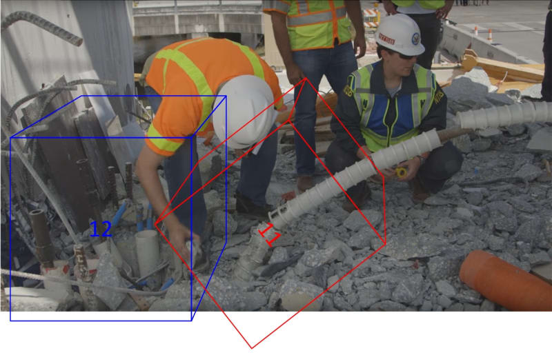
Gwideman...your picture
gwfiub_04_11-12-deck_close_view_jlb0u4_isz5mz.jpg


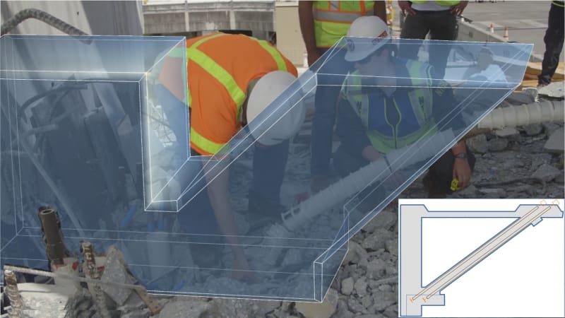
As mentioned in my last post...the area you have blocked out in blue...there is a square block of concrete gone in the top section of the deck. The pipe 2 on each side of member 11 have not been grouted. It looks like 11 sheared and punched out a square. This is punching shear except it is in the horizontal plane not the vertical. This piece of concrete is what we see in Meerkat 007 video at 0:17 seconds protrude out horizontally in line with the deck.
 
waross:

If member 11 crushed (implying it was under excess compression forces for its cross-sectional area for that time of concrete curing), the entire lower deck was almost certainly under tension before any other event happened - because the bridge was supported only at the two extreme ends.
The upper canopy was under some compression - but the actual compression stress in the canopy varied between each member and between each node since the intersection angles varied at every node, and the distances between every node varied as well. Since some of the angled members were in great relative compression, and some in mid-compression (compared to the average member), could some members have been in tension?
 
...was just thinking... this almost looks like a 'big' strut and tie system...

Dik
 
From the April 2015 FIU-UniversityCity Prosperity Project - Pedestrian Bridge (page 13):

FIU-Pedestrian-Bridge-Design-Criteria-2015-05-06_REV.pdf said:
5.9 Deck Systems
The bridge superstructure should be primarily structural steel with concrete walking surface. The design should avoid use of non-redundant, fracture critical members.

 
IEG:

Missed the fine print...

Dik
 
Where are the rebar linking No. 11 and 12 with the walkway?

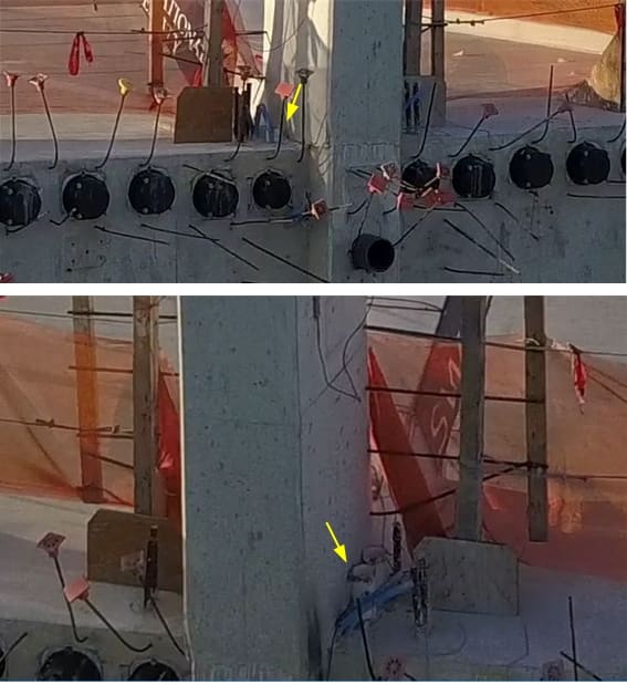
The following photos were provided by gwideman on 23 Mar 18 10:54

They depict the locations of four plastic ducts, two on each side of No 12, before the collapse.
gwfiu_11-12-deck_annot_04_cvwvuv.jpg


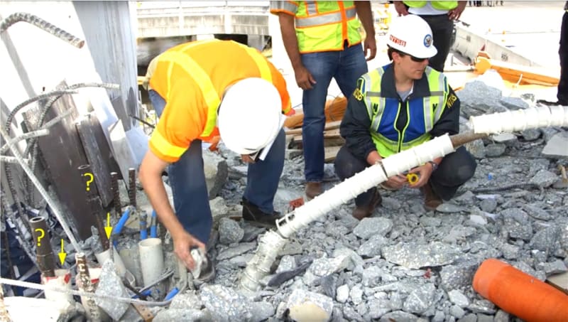
After the collapse gwideman showed the walkway deck with rubbles. The deck rest on the ground and tight against the abutment wall after the collapse.

gwfiu_11-12-deck_annot_03_tfiggf.jpg


The four plastic ducts are now visible but No. 12 member has gone. The long PT duct shown belong to No. 11. Thus the original footprint of No. 12 and 11 on the deck is in the above photo.
VolsCE84 has drawn the positions of No. 12 & 11 but his diagram appears too large and covers the 4 plastic ducts.

Do we not expect some reinforcement linking the No. 11 & 12 with the deck? The short vertical steel bars were started bar cast outside the No. 11 & 12 according to the first two gwideman photos.

I found it disturbing that no significant reinforcing bar from No. 11 & 12 embedded in the walkway deck. Anyone care to comment?
 
I wonder what impact this will have on the next bridge, and, whether it will be placed in the same location...

Dik
 
IEGeezer,

I believe the "FIU-Pedestrian-Bridge-Design-Criteria-2015-05-06_REV" is just a wish list of the Owner FIU. The Owner selected MCM/Figg's offer, accepted the contractor's design and awarded the contract.

It is also difficult to say the bridge superstructure isn't primarily structural steel because the finished product is similar to a cable stayed bridge except those who can read the design know the primary strength comes from the post-tension bridge. The final bridge isn't hang by cables but 16" diameter steel pipes.

The steel pipes can carry a significant amount if not the full load. Their main benefit, acting as spring supports in the interior points, is to raise the fundamental frequency of the footbridge to avoid resonance by the pedestrian traffic. They are also acting as redundancies for the structural system.
 
gwideman said:
Regarding 11-12-deck, I wonder if a structural engineer might comment on how such joint systems work typically? What they might expect to see inside this bridge?

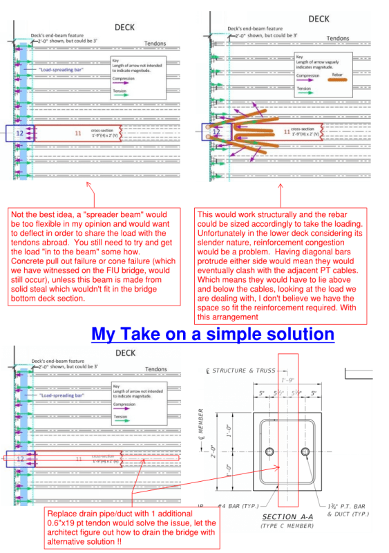
Ok, sure, I'm a Structural Engineer, see right at the very bottom for my solution and what I would expect for the joint detailing.

gwideman said:
So perhaps the idea is like in the following image: #11 presses on the deck end beam, which in turn acts as (or contains) a very stiff bar distributing the horizontal load to the tendons. Is that feasible?

gwideman said:
Or might the horizontal load from #11 be constrained by rebar that folds back south (rightward) into the deck for some distance: Either rebar in #11 folding like a hairpin under #11 into the deck, or L-shape rebar, with one leg vertical in #12, and a horizontal leg into the deck. Those horizontal legs in the deck could be long enough to spread compression broadly into the deck, to be resisted by the tendons?

Please see under for my comments on your schematics.

Bare in mind that according to my numbers, we only need one more 0.6"x19 Tendon running straight through the middle for the joint to work.

Reply_to_eng_tips_1_bwbjku.png
 
saikee119 said:
The steel pipes can carry a significant amount if not the full load. Their main benefit, acting as spring supports in the interior points, is to raise the fundamental frequency of the footbridge to avoid resonance by the pedestrian traffic. They are also acting as redundancies for the structural system.

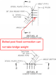
You are correct on almost all counts. Redundancy however may be questionable. I agree that the CHS sections "can" take significant loading, but again the weak point is the connection which is a post-fixed bolted connection to the concrete top deck and the pylon. If the bridge wants to come down, with the cables attached with this detail, the CHS sections won't stop the bridge from coming down.

It also raises an interesting further question. I would assume that the design engineer would want these CHS sections to be attached as late as possible in order for the bridge to move and deflect as much as it can before the CHS's are fixed so they don't attract any unwanted loading that the connections may not have been designed for. Considering that the long term deflections of the bridge will continue well after the construction team is finished on-site, I'm wondering how the connections would have fared in the long run as they are forced to take more and more load with time as the bridge relaxes under creep and shrinkage.

As stated above, this would not pose a life safety issue at all however would begin to alter the frequency characteristics of the stucture and may begin to perform inadequately under vibration excited by foot traffic as the connections begin to yield.

Cable_Stay_con_mark-up_tzsg8e.png
 
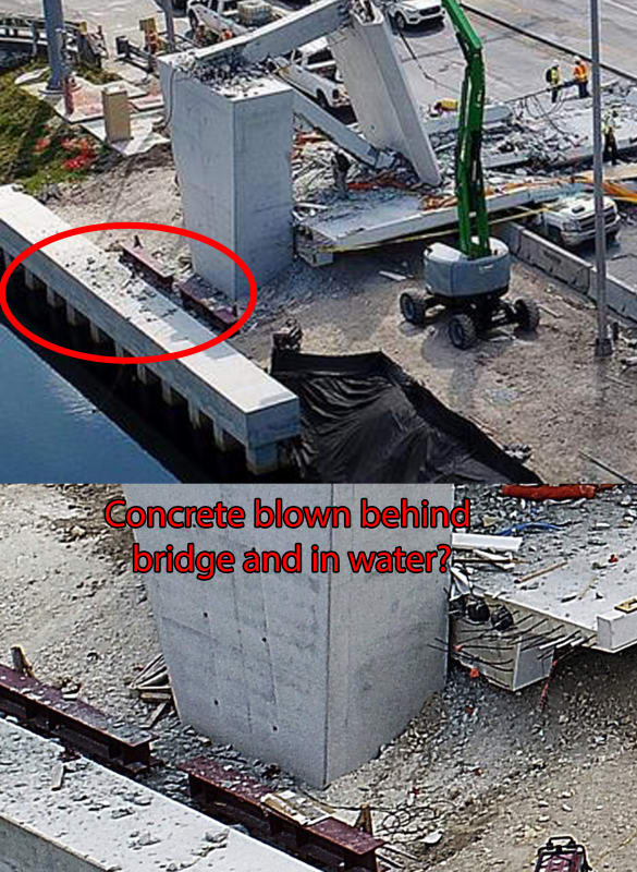
I believe that the picture of the bottom deck in Incentives post above clearly shows that the tendons in the deck or the deck itself did not blow "out the back" but that section 11 and 12 sheared cleanly off at the deck due to inadequate shear capacity. Reliance mainly on shear in plain concrete with moments, torsional shear, possible added shear from temperature effects and near the location of a cold joint, just plain folly in my opinion. Shear lag in the deck would also be a factor here and apparent lack of PT tendon across the deck near the anchorage to help confine the deck concrete. Big thing is that 11 itself appears to have only nominal stirrups which would not give 11 itself adequate shear capacity. It could well be that 11 also did not have adequate moment capacity in both axes.

 
INCENTIVE said:
Is it the consensus that the concrete seen protruding half a second before the collapse is just the camera angle/illusion?

In my opinion it would be extremely hard to critique the failure mode of the bridge using the video footage alone, considering the footage was taken so far away.

Deflections and yielding of only 10mm would be enough to start a collapse of such a structure given that if is a truss and is not designed to bend primarily.

I don't believe the investigators would use the footage as a large percentage of support evidence in their findings, just to back up theories. At the end of the day, everything should (and can) be proved theoretically given the as-built drawings and an engineering analysis. I must stress again that this is not a complex sturcture and indeed a truss is something we all learn in Engineering 101 at university. Someone indicated previously that "months of analysis" would be needed to check these things, this is simply not the case. Engineers are not scientists/chemists, we like things to be simple, simple to build and simple to analyse. I am relatively comfortable with my pen and paper appraisal which took me 15 minutes to scribble to determine that there is a potential problem with the support node at junction 11/12.

There were questions about ductility and no warning given before the collapse earlier in these threads. Unfortunately the failure mode that I have speculated on earlier with my pen and paper hand calculations is not a ductile failure. If the PT cables weren't adequately developed or anchored near the support node, then this is brittle concrete failure as it shears out the edge of the bottom deck, litte/no warning will be given. Unfortunately this is unavoidable and codes around the world don't adequately address this, it's something we as design engineers have to deal with, much like punching shear failure can be brittle in nature as well.
 

SheerForceEng,

Re-examining the drawings I tend to agree with you that congestion will be a problem if the designer details some rebar from No. 11 to pass the stress into the deck. The transverse and longitudinal PT systems effective form barriers difficult if not impossible to thread through large diameter rebar.

Apart from using the drainage pipe position to add an additional PT line which will certainly help the situation. An alternative is to pass the rebar from No. 11 into the downstand section which some call end beam that has a beefy dimension of about 18'2" long by 4'2" deep by 2'10" wide. The end beam embeds all the longitudinal PT anchors below which there is ample space to bond reinforcement from the No. 11 to develop their full strength.

Another alternative is to weld a piece steel plate to say two sets of anchor PT plates on either side. The steel plate has to be at least same thickness or thicker than the PT anchor plate. If No 11 shear outward they have to take out at least 4 sets of PT tendons. To avoid bending the additional plate needs stiffeners which can be embedded inside No. 12.

The vertical member No. 12 can also be made strongly connected to the end beam to form an effective restraint or buttress.

I believe as an engineer we could all find different solutions to make a stronger connection for No. 11 & 12. The question now is has this connection been adequately designed or not overlooked.
 
sheerforceeng said:
but again the weak point is the connection which is a post-fixed bolted connection to the concrete top deck and the pylon

I don't know how they were to be fastened, even through bolting to the plate on the other side... maybe we'll never know...

8 - 1-1/2" dia bolts are 'serious' attachment, depending on the grade of steel, capable of providing an attachment resistance of 400K or more. As I've noted before, the 'cable stays' are a bit of an enigma, they are supposed to be decorative, but offer substantial resistance. It would be a challenge to determine how the walkway would have functioned with them.

Dik
 
SheerForceEng,

I agree that the 8x1.375" diameter bolt connection for the stayed 16" diameter pipe is inadequate to realize the full strength of the pipe. My guess is this may be deliberately arranged as if the stayed pipes were fully load bearing the pylon will be bent due to the north side not symmetrical to the south side.

If the bridge is self-standing the tension in the pipes will not matter much to the overall deflection as the bridge will be much stiffer while the steel pipes will behave like soft springs.
 
Status
Not open for further replies.

Part and Inventory Search

Sponsor