Eng-Tips is the largest engineering community on the Internet

Intelligent Work Forums for Engineering Professionals

  • Congratulations waross on being selected by the Tek-Tips community for having the most helpful posts in the forums last week. Way to Go!

Miami Pedestrian Bridge, Part IV 74

Status
Not open for further replies.
Tomfh said:
Apologies if it's outlined above, but can someone tell me the load in #11,
Not exactly. It was 1615 kips plus whatever additional load from the post-tensioning bars that were in use, which is unknown but the 2 bars together are easily capable of adding another 600 kips.

So say somewhere between 1615 kips and 2215 kips. and you will likely be right.

Tomfh said:
and the ultimate capacity of #11?

I estimate that the design of the member #11 appears to be for about an ultimate capacity or maximum allowable design factored load of about 2,000 kips but we are missing exact information on the exact quantity of steel reinforcement bars which was added. It might easily be 100 kips more. So say 2,000 to 2,100 kips. However beware because with ultimate capacity, on the one hand there is what the design intends and on the other hand there is what the construction firm actually build which can be two quite different things.
 
Ron said:
Has anyone seen a concrete mix design or any test results of the concrete?

Ron,
I posted a reference back in Thread I of this topic.
It related some special additives for the concrete: [red]The bridge is also made of self-cleaning concrete. When exposed to sunlight, titanium dioxide in the concrete traps pollutants and turns them a bright white, the university said.[/red]

Not sure if that would be a reason for your observations or not.


Check out Eng-Tips Forum's Policies here:
faq731-376
 
Peter Dow, Thanks for the corrections.

I single out the strength reduction factor because it is a safety factor used in the design. If the structure fails then we should be interested in the actual stress relating to the actual strength.

Suppose the concrete fails by compression I would think the actual tested cylinder strength, say using the average with statistics, would more relevant than the cylinder strength specified in the drawing.

Lastly No. 11 top end is clearly a bending failure due to the member rotates excessively at the joint while the bottom end has concrete broken away and detached from the walkway. The majority of No. 11 was still standing and able to remain so despite its lower PT rod was forcibly pulled out.
 
Peter Dow said:
ultimate capacity or maximum allowable design factored load of about 2,000 kips

Could you clarify, is this the load you expect it would actually break? Or is 2000 a factored capacity?
 
Like Ron, I believe the paucity of mild steel reinforcement is the major issue. My opinion, for what it is worth, is that all the joints were suspect, not just whichever one(s) failed first.

This was, as dik said, a large scale strut and tie example, and in this case the anchorages failed to connect with each other.

As to the drainage, architectural considerations overrode structural logic.
 
My estimate for the load on 11 is smaller (see my previous post above). Based on the member sizes in the conceptual design, I calculated a reaction at the north pier of 910 kips (slightly less than the 950 kips in the press accounts).

A portion of this total reaction is the dead weight of half the last span of the base slab and half the last span of the canopy slab. Those forces are not carried by 11.

In addition, the weight of 12 is not carried by 11.

Making those adjustments reduces the unfactored dead load force in 11 to around 1150 kips, plus PT.
 
The Traffic Camera footage of the bridge collapse was supplied by the District 6 SunGuide Transportation Management Center, which was retrofitted in 2015. There are 18 work stations on the first floor, 15 managed by the FDOT & 3 by MDX (Miami-Dade). On the second floor are another 18 work stations dedicated to the Florida Highway Patrol. From reading their literature, it seems that once they had a loop of the collapse on a desktop screen, the system automatically generates a "tour" and assigns an ID. To say it was discarded by the servers doesn't apply. The specifications for the upgrade included new keyboards with keys dedicated to recording video of what is displayed. The arrival of first responders to the scene was so fast some 911 callers were still on the line with the 911 operator. Either the authorities just are not releasing the video or there is something very fishy going on.

Specs Final
Link
 
 http://files.engineering.com/getfile.aspx?folder=d9ff14d5-c5af-4a6a-86a3-d24782b5a8dc&file=20180316miami-feluljaro-baleset.jpg
I've been having a difficult time letting go of that image of #11's lower tensioning rod protruding out the top with jack still attached. I thought surely it'd snapped as suggested by the Youtube "Smoking Gun" guy but finally realized that is likely a red herring.

Ingenuity's image above clicked.

Bottom end of that tensioning rod came down with the walkway. So it moved from diagonal to almost perpendicular as shown in orange.

fiubridge26_evufvi.jpg


That's a lot less distance . Of course it might well have got pushed out the other end.

Thanks for the great discussion, folks.

Never trust a computer with anything important...
 
Do we know when the PT cables in the bottom deck/chord were stressed? Were these cables stressed after the entire truss was poured or was the bottom deck poured, then stressed, then the diagonal/verticals poured and so on?

If the cables in the bottom deck were stressed after the vertical and diagonal members and top chord were poured, this would put significant added stress to both the tension from the bottom deck trying to find its way into the node joining members 11+12 (thus magnifying the pull out failure eluded to earlier) and it would also result in some of the PT force finding its way up into member 11 as well thus further increasing the compressive demand on this member itself.

There is a large amount of PT cables in the bottom deck doing basically nothing near the node structurally but depending on the sequence of stressing and pouring, a large majority of those tendons will be actually working counter-productively against the node itself.

The tension from the bottom deck entering node at members 11/12 has already been proven to be significant compared to the reinforcement provided based on the apparent detailing, this would make matters much much worse potentially.
 
Old Jim,

Your observation is what I thought too. This PT rod is 1.75" or 45mm diameter and does not bend easily. It was dropped from a diagonal position to the horizontal position. One end is firmed anchored at the base of the deck/end beam and can't move. The other end is totally free, being adjusted with a jack or torque wrench, so it pushed freely outward. The exposed extended distance, which gave a Youtuber the idea of a smoking gun that the rod has broken under the post tension, should be the difference between the diagonal and it horizontal projection of your triangle, adjusted for the small curve bit.

Additionally there has been a report by the authority that the workmen had completed the tension adjustment of the PT rods iat the south end, moved to the north end, finished one PT rod and was doing the second one when the bridge collapse.

If this working sequence were correct then it would be possible that all the fully adjusted PT rods have not failed in tension. The last PT rod has a jacked still attached after collapse. It is now known the bottom PT rod of No. 11, able to rip the surface concrete layer plus all the steel stirrups out and is still visible inside the broken duct. The duct has also been intermittently cut by pulling out of each the steel stirrups, as seen from meerkat007 photo.
vlcsnap-2018-03-26-02h21m45s023_ib6snl.png


A possible conclusion is none of the PT rods in the truss has failed in tension. This is in fact common sense as the PT rod is often controlled to stress to only a specified portion of its breaking load.
 
Tomfh said:
Peter Dow said:
ultimate capacity or maximum allowable design factored load of about 2,000 kips

Could you clarify, is this the load you expect it would actually break? Or is 2000 a factored capacity?

2000 kips is a factored load which is a resistance factor of 0.65 less than the nominal load capacity which is 2,000/0.65 = 3,076 kips.


I would expect a break at any load greater than factored load (2,000 kips) but I would not know when to expect it.
I would expect an instantaneous break at any load greater than the nominal load capacity (3,000 kips).
 
I just want to add my personal view on (1) cracks found on north side and (2) the brittle failure

Cracks are common in concrete and as they can easily introduced in construction by poor curing (cement hydrates, wet concrete heated up and controlled to cool down uniformly - shrinkage cracks). Cracks found by Figg have been dismissed not safety related and no one so far responded. That is true engineering professionalism because we have no information on its locations, widths, lengths and depths. Therefore we should not speculate. When cracks are reported to me I normally demand a mapping of it, full set of photographs and monitoring of their growths with time so that the root cause can be established before any mitigation can be formulated. If the reputable Figg engineer has not got a record of the cracks the truth impact of the reported cracks will never be known. An experience engineer will make a record of it if one deems important. If one wants to see the best concrete, usually mixed with some cement replacement agents like micro silica (silica fume), PFA and GGBS to minimize cracks, one can go to Paris Charles De Gaulles airport or the one in Oslo and will find cracks there. Cracks are important if they can be proved to be stress related in service condition.

The bridge is just an "I" beam with the web replaced by diagonal members. I know many will argue it is more complicated but the structural arrangement will make the bridge substantially behaving like an "I" beam. Individual member may have extra bending moments, shear and deflections which can be considered secondary in the failure mechanism assessment. FEM analysis can reveal how much areas of the top and bottom flanges effective in acting as top and bottom chords. The photos of the first north bay now shows No.11 and 12 detached cleanly from the deck. One video recording show bulging out of the end member near the deck level. There is strong evidence to support No.11 did not remain static and its angle with No. 10 was opening up. That is the point of no return and a vicious circle because more load is passed onto No.11 forcing it to move out even more. Once No. 11 fails its duty to act as the web the bridge at the north support has to rely on just the walkway deck (or bottom flange of the I beam) for support because the web and the canopy (top flange) no long participate to resist the load. In the original design with No. 11 intact the top flange is in pure compression while the bottom flange in pure tension. When only the deck carried the load at the north end the flat deck will experience compression at the top face and tension at the bottom face, a condition it is never designed to withstand. Therefore once the No.11 moves away or unable to be restrained the bridge must fall. There is no ductility in this failure mechanism if the I beam changed into a flat plate at the north abutment.
 
saikee119 said:
When only the deck carried the load at the north end the flat deck will experience compression at the top face and tension at the bottom face, a condition it is never designed to withstand

I guess In hindsight, it should have been able to withstand that scenario to meet the redundancy requirement of the RFP.
 
XR250 said:
I guess In hindsight, it should have been able to withstand that scenario to meet the redundancy requirement of the RFP.
That would be an impractical requirement to specified.

The current design as an "I" beam is 18' tall with top flange separated from the bottom flange by the central truss.

In the first north bay if the truss member No.11 fails it duty the structural member left to resist the load is the walkway deck maximum 2'-1" thick at the middle tapering to 9-1/2" at the two extremities. Such demand is beyond the scope of concrete over the 175' span. Remember the lever arm, defined between the centers of the resisting tension and compression area, must drop from about 9' to 1' against the same disturbing moment at the failure point.

MCM/Figg design does deserve credit had collapse not happened and had the steel pipe stays installed the 10 hangers will provide some usable structural redundancies.
 
My summary of the issues and actions so far, mainly so I can get my head around and hopefully to help anyone joining the discussion just now. However a good perusal of the parts I, II and III is highly recommended to avoid raising the same point which has already been addressed and responded to, sometimes in great detail.

The Bridge in question is more than a little strange and non standard in a number of ways.
1) Although the final pictures of the bridge, intended to be a "signature" bridge linking either side of a wide highway, show what appears to be a cable stayed bridge, this in in fact two separate standalone concrete spans with the appearance of a cable stayed bridge. The "cables" are in fact 16" hollow pipes which may take a small percent of the load and apparently were going to aid in preventing the bridge vibrating, but essentially cosmetic.
2) The 175 foot span is a concrete rigid truss / beam design with the internal members aligned with the "cables". This creates an asymmetric design which would appear to load up one side of the bridge members. The rigid structure of the concrete means the bridge is not as easy to analyse as a steel truss bridge would be.
3) The Bridge was being used in part as a showcase for the universities Accelerated Bridge Construction idea whereby the bridge was built to one side of the road and then moved into place in a one day period to reduce road closure / diversions. This precluded the use of a classic cable stayed bridge.

The collapse as captured on a highly fortuitous dash cam occurs in a split second from what can be seen on the video and hence it is, IMHO, impossible for anyone to be 100% certain of which part of the structure failed first. The consensus in the near 800 posts made to date is that something went wrong with member 11, either punching through at the base with member 12 or at the top with member 10.

At the time of the collapse, member 11 was, apparently, being de-tensioned, following the de tensioning of member 2. The two tendons in both of those members were required as a change to the original design. In the original design the span was lifted and moved using SPMTs located at the extreme ends of the span. A design change to make the bridge 11 feet wider to allow for future highway expansion meant that the support points moved inboard. This placed members 2 and 11 under tension during the move, instead of their normal life of compression. How much these changes made overall to the design and how well they were incorporated and analysed we can only guess at and I'm sure it will form part of the NTSB investigation.

All the information used by posters is that available in the public domain, using initial drawings, videos from NTSB and individuals, other photos and record sources. No one has access to the designers calculations, analysis, construction drawings, site modifications, tests, or testimony of individuals concerned. This is the remit of the NTSB. Therefore any and all comments are educated conjecture, but in the main very informative.

Most of this conjecture over the last few days has concentrated on member 11 and its possible / probable failure in some way. Whether this is as a result of a shear failure / punch out at the base of member 11/12 (my current favourite theory) or at the top of the column with member 10 I think is very difficult to say based on current evidence. Most people favour the fact that the root action was the release of tension in the final lower tendon in member 11 which would appear to have provided, perhaps unintentionally, some level of shear capacity in the joints at one end of member 11. How these forces were supposed to be contained within the structure and whether the partial build was properly analysed is not known in any detail.

Whatever happened in the failure happened very quickly indicating a lack of ductility and redundancy in the structure. Whether any of this was assisted or affected by the cracking noticed on the structure in the day or days beforehand is not clear, nor where the cracking was noted. There were some reports that this cracking resulted in a 2 hour discussion onsite followed by the actions to de tension (we all assume) the tendons in members 2 and 11. Again why this work then took place on a brand new bridge above live traffic is clearly an error in retrospect and again should form part of the NTSB investigation.

I think the general level of discussion and theorizing on this particular thread is to a high level of engineering design and experience and a great credit to Eng tips and those who post within it. I suspect we will run out of new areas to look at until the NTSB release their initial discoveries which may provide further information or at least discredit some of the collapse theories.

We can all learn a lot from failures and for me the key lesson here is to actually recognize when something is not design as usual and that the normal simplifications and analysis may not be accurate.

LI


Remember - More details = better answers
Also: If you get a response it's polite to respond to it.
 
Yup, this emerged a few days ago. Impossible to know how this change impacted the design other than it meant moving the transport locations to further inside and need tension support to members 2 and 11.

Remember - More details = better answers
Also: If you get a response it's polite to respond to it.
 
Some engineers also have a tendency to "overanalyse" by way of computer software and FEA modelling, to the point of relying on these tools more than they should (thus overcomplicating things). I have no doubt that you can input all this data for the members into a computer model and it will all work (in theory on the computer scree). But then there is a point where you need to extract it from your computer model and put it onto drawings and get it to work in the real world. This is where detailing of the connections is key and basic engineering principles need to prevail (not complicated).

Preach on, Brother SheerForceEng! I have no doubt the model worked exceeding well. It's a shame they had to make a full-scale mock-up of it, and do so over traffic.

Sadly, I suspect that when all is said and done various codes will respond by increasing an inch (25.4mm) thickness and the only reason they won't be thicker is that they will have simultaneously decreased their fonts.

Meanwhile, I wish they would decrease in thickness by 25mm. Sure, we might wind up using a bit more concrete and steel here and there but the upshot might be that we would feel less emboldened to create over-complex structures that skinny designs down while theoretically meeting the all the various load cases. Which is not to say they wouldn't necessarily work in real life; they will...well, unless we overlook something fundamental.
 
So many good comments since I last checked this thread, and too many to comment on individually. I'll just add a few more thoughts on top of everyone else's regarding this hypothetical failure mechanism (still my preferred).

Thanks to Meerkat 007 for image:
Meerkat-1_xhw4zq.jpg


Wouldn't plane A-A, being smaller in surface area than B-B, fail in shear before plane B-B? I realize that loading and reinforcement is not equal for both, but this looks suspiciously weaker.
 
Electronics related newbie here... structural engineering is more interesting and REAL - thanks to all for contributions here.
Pls forgive any ignorance and correct me where wrong. I'll try not to repeat (much). Special thanks to LittleInch for the summary.

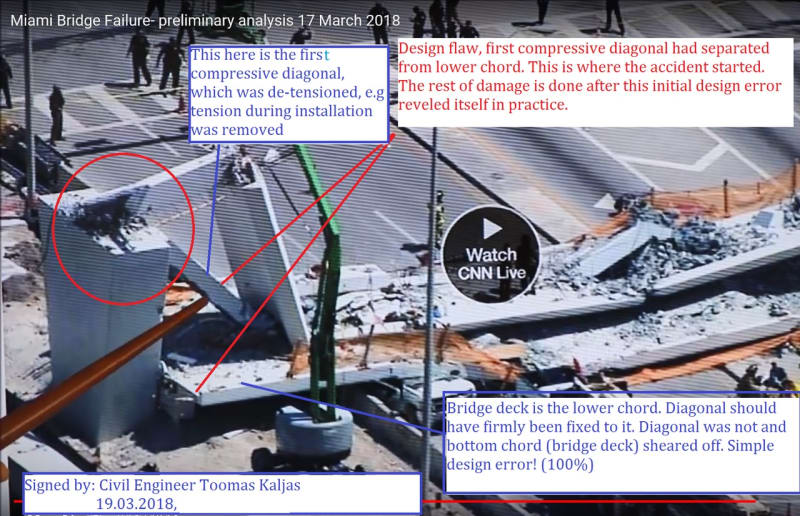
A structural engineer posted this and said the first diagonal compressive connection failed, and if PT rod broke (per "smoking gun" video) this alone wouldn't cause failure.
00-Cause_of_failurein_Miami_bridge_2018.03.19_preview-j_p2qsq0.jpg


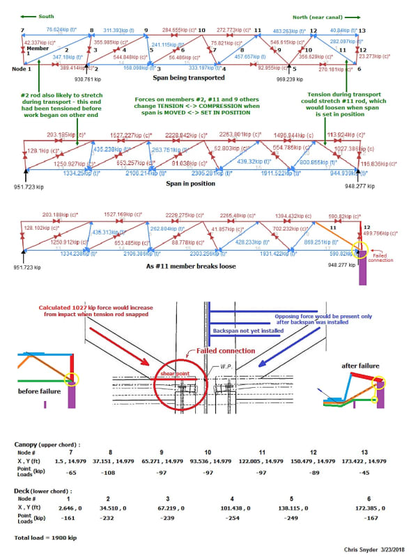
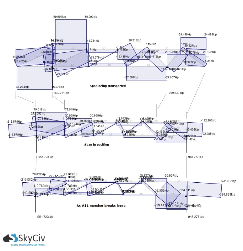
I estimated/calculated centerlines from prints to get nodes (end members not vertical as center of member(s) contact points were used instead of trying to figure center of force), and point loads were estimated by calculating volume of deck, canopy, members, and blisters then dividing into total weight - load was split midway between centerlines and distributed from canopy/blisters to upper nodes, and trusses/deck to lower nodes . Weight came out to 165 lbs/cu ft, which seems heavy (volume calcs didn't include 'gussets'/radius where members meet)- I didn't estimate percentage of steel or air in ducts (calcs may be within 5-10%??). I used online app (SkyCiv) to analyze forces with span being moved (supports not actual SPMT placement - I just wanted to see forces change direction on #2 and #11), with span in position, and when #11 first sheared.

fiu_bridge_j_khbiwf.jpg


Shear forces under same conditions
FIU_Shear_forces-j_g040tw.jpg


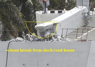
#11 was pushing against the edge of the deck - when the bridge was completed, force from the backspan would have countered this. I'd expect a break on the deck as ShearForceEng shows in 25 Mar 18 00:42 - odd how the break of #12 is clean from deck
deck_break_whkbtm.jpg

04-clean_break_of_12_from_deck_hyvmrg.jpg


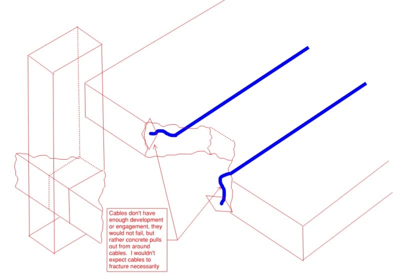
The PVC tube under deck, cable ducts close by, and little concrete at edge creates a weak point. I'd like to see casting/rebar specs.

The engineer (Toomas Kaljas) who posted the first photo says software may not analyze connection strength, and that some engineers depend too much on software. He stresses this and discusses connection failures in his analysis of the Latvia Maxima collapse.


From the "smoking gun" video, this news video (I agree the "puff" may be the corner of deck from changing angles)
"NTSB Focuses Collapse Investigation on North End of FIU Bridge"
and the NTSB release,
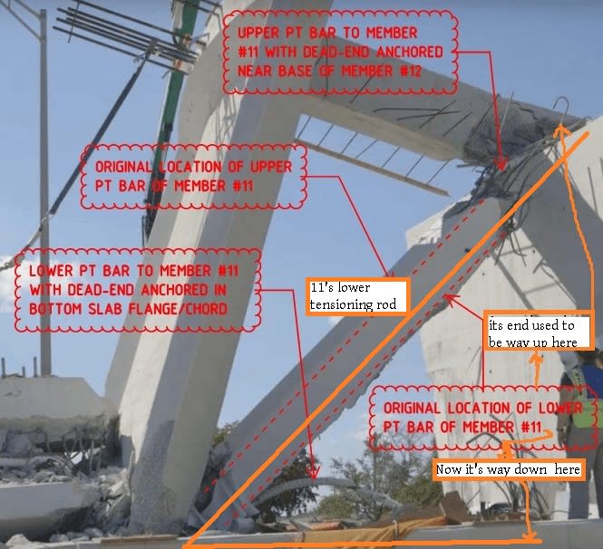
I suspect the lower tension rod in #11 was being tightened and broke. When this happened, whatever force it took to propel the rod/jack (~400 lbs?) an estimated 6 ft from its position may have created an opposite impulse toward the bottom end of #11 and triggered the shear... I can't visualize this, but Newton's third law is true (this is not like a shotgun blast pushing a load, as the force was in front and pulled the rod out).

I have a question about the PT rod specs: Why are there none for #11 and 12 and some others in the table? These show 200-280 kips for most and 320 for #15 (sorry if answered elsewhere - I didn't read some in parts 2 and 3).

From one article, I sensed this final adjustment may have been dealing with closing the crack(s). In any case, it was foolish to do this work with traffic flowing. There was too much emphasis on building this bridge with minimal effect on traffic flow.
 
Status
Not open for further replies.
Back
Top