-
2
- #1
Navigation
Install the app
How to install the app on iOS
Follow along with the video below to see how to install our site as a web app on your home screen.
Note: This feature may not be available in some browsers.
More options
Style variation
-
Congratulations TugboatEng on being selected by the Eng-Tips community for having the most helpful posts in the forums last week. Way to Go!
You are using an out of date browser. It may not display this or other websites correctly.
You should upgrade or use an alternative browser.
You should upgrade or use an alternative browser.
Miami Pedestrian Bridge, Part IV 74
- Thread starter hokie66
- Start date
- Status
- Not open for further replies.
Lo, Dik, Arcie,
I still also have mine, just in case of the power outage and for sentimental value.
The exact wording of the code is:
Superstructure - Check Strength I, II, Service I, II, (III,) Fatigue.
For large bridges, also check Strength III, IV, V, Extreme.
The question is - was this bridge considered a large bridge? Was the Strength IV and V checked?
The SF = 1.7 - 1.8 was used for quite long time, without any major problems, using proven allowable stress design, and thanks to this many corroded or spalled bridges are still surviving.
I agree that he codes are becoming extremely complex, with constant changes and modifications, and difficult to use at best. And by relying on the software could be tricky, as I have seen the analyses of a not large, but a major bridge completely wrong, due to mistake in the input files. Still the results were looking impressive and close to reality enough to be taken as credible, just for a while.
The links were helpful, but not answering the main question - what exactly was used for the design? Was the cracking load for the span established and compared to the unfactored loads? I think that in the complexity of the codes this basic principle get lost.
How the joints supposed to be designed for shear? By relying on the strength of concrete, and carrying excessive stresses via mild reinforcement? AASHTO clearly allow such approach, and it the designer responsibility to decide how to proceed. Cracked concrete has no shear capacity, so when the steel is missing, or undersized, shear failure is to be expected.
Well with a span over 70 ft it is considered Long Span by definition.
This may be what put the bug in FIU for a Cable Stayed Bridge. FIU Webinar: "Applying ABC Concepts to Long-Span / Complex Bridges" Link
The second pedestrian bridge Don Burnett Bicycle-Pedestrian Bridge (Mary Ave) in Cupertino CA cost $14.8 Million in 2009 Material: steel - Total length: 503 ft (153.3 m)- Height: 79.9 ft (24.4 m) Longest Span: 325 ft (99.1 m) - No. of spans 3. Link
- Thread starter
- #6
-
4
- #7
Further details of the 11-12-Deck connection area, (which has become of interest here, though not to argue that other areas are ruled out, particularly the junction of 10, 11 and canopy).
From videos posted at: which was mentioned in this forum by jrs87 -- thanks.
A couple of images from the bridge shortly before move.
Main point of interest: the approach of #11 to #12, and to the deck. Note the "fillets" between #11 and #12, and between #11 and deck, which I had not previously noticed. A yellow arrow indicates white pipe with red tape or paint on rim that correlates to a later image.
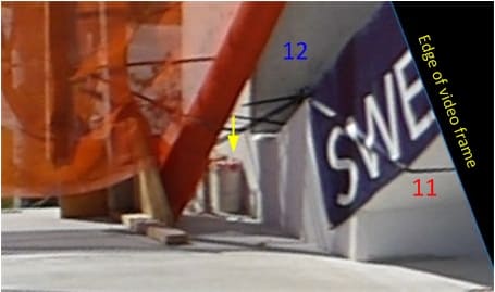
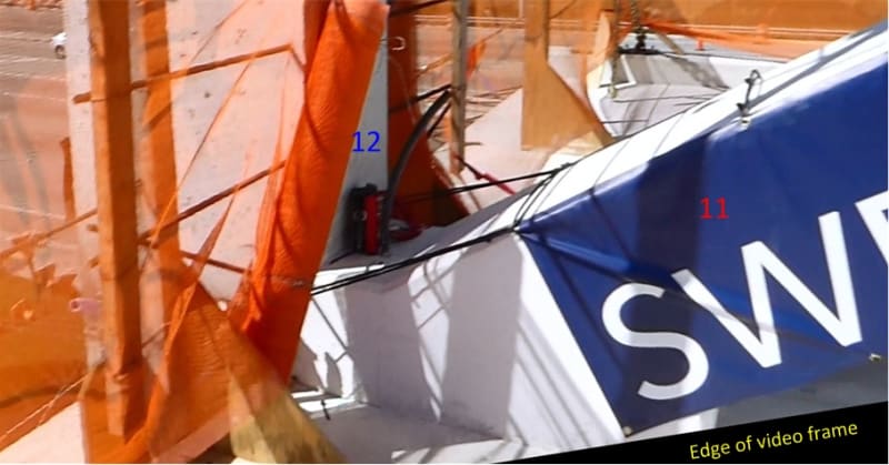
The area pictured above corresponds to the area captured from the NTSB B-roll footage, which I previously posted, wondering the function of the rods marked with yellow "?". These rods are enclosed in white plastic pipes; the one on the near side bears red tape/paint:
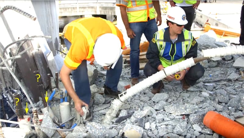
I had previously thought that these rods and their enclosing pipes were within the footprint of #12, but apparently, from pictures above and below, they are just outboard. I also thought that the other pipe on each side was perhaps part of services to be supplied up inside #12, perhaps along with additional channels in the void between the pipes. However, to me it now looks like the void between these pipes is simply where the base of #12 tore out at some stage in the collapse, leaving connecting rebar bent over to the extreme left of the picture.
Steve Nuchia suggested these rods might be for position keeping. I think the following images show that the rods indeed tie the bridge to the pier, though they are not in the position shown on the proposal drawings, but have moved inboard. I'm thinking that the protrusions seen on the pier were extended in some way after positioning the span, so as to stick up through the deck's end-beam and out of the white pipes on each side of #12. These images are from drone footage during the move.
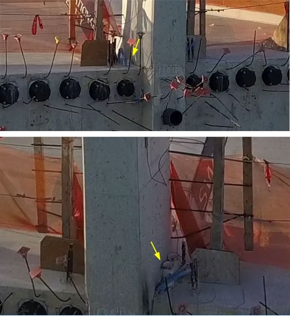
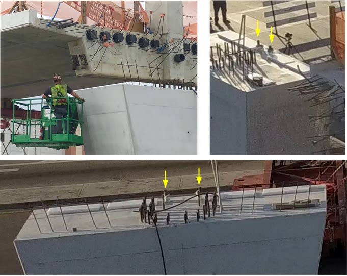
I imagine at some point we'll get to see photos of the cracks that were reported, and see whether they are in the 11-12-deck neighborhood.
From videos posted at: which was mentioned in this forum by jrs87 -- thanks.
A couple of images from the bridge shortly before move.
Main point of interest: the approach of #11 to #12, and to the deck. Note the "fillets" between #11 and #12, and between #11 and deck, which I had not previously noticed. A yellow arrow indicates white pipe with red tape or paint on rim that correlates to a later image.


The area pictured above corresponds to the area captured from the NTSB B-roll footage, which I previously posted, wondering the function of the rods marked with yellow "?". These rods are enclosed in white plastic pipes; the one on the near side bears red tape/paint:

I had previously thought that these rods and their enclosing pipes were within the footprint of #12, but apparently, from pictures above and below, they are just outboard. I also thought that the other pipe on each side was perhaps part of services to be supplied up inside #12, perhaps along with additional channels in the void between the pipes. However, to me it now looks like the void between these pipes is simply where the base of #12 tore out at some stage in the collapse, leaving connecting rebar bent over to the extreme left of the picture.
Steve Nuchia suggested these rods might be for position keeping. I think the following images show that the rods indeed tie the bridge to the pier, though they are not in the position shown on the proposal drawings, but have moved inboard. I'm thinking that the protrusions seen on the pier were extended in some way after positioning the span, so as to stick up through the deck's end-beam and out of the white pipes on each side of #12. These images are from drone footage during the move.


I imagine at some point we'll get to see photos of the cracks that were reported, and see whether they are in the 11-12-deck neighborhood.
@Ingenuity:
Thank you for your detailed response to my question in Thread #3.
When you look at the full picture of the member, putting things into terms of applied stress to the full section makes a lot of sense.
I think I was failing to wrap my head around this... as a mechanical guy who deals with a lot of HSS sections, I'm used to a 12" square member (just as an example) having a cross secitonal area of <<<< 144in2. Concrete is so different, even in little ways like that.
With that said- how do you account for transfer of all of that PT tendon load into the concrete so that the full section is developed?
The anchor for the PT tendon can't cover the entire section... is the anchor sized to keep the applied stress below some target value (based on concrete properties + design factors, etc), and then there is some stress distribution through the section as internal shear forces spread that load?
-
2
- #9
Meerkat 007
Computer
Member #12 damage overlap.
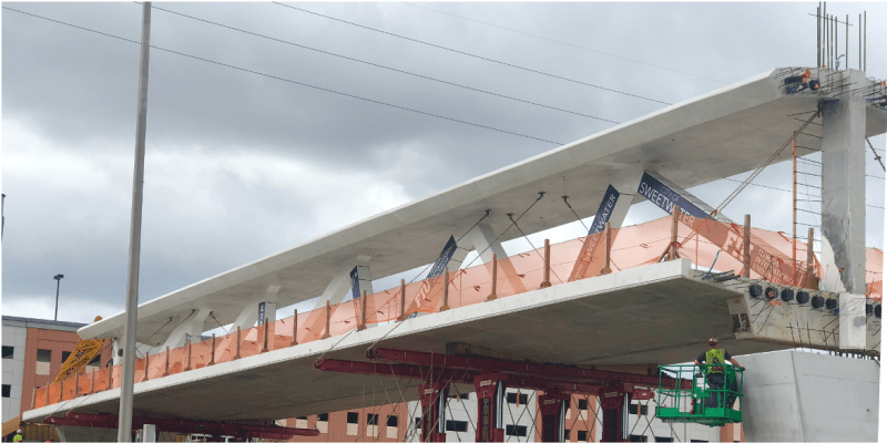

Very interesting image + graphics by Meerkat 007.
I've now seen a couple of images that make it seem fairly certain that the junction of #12 at the canopy remained intact and rigid 90 degrees.
If that is the case, then the initial action would not have been crushing and shortening of #11, but rather the junction of #11 and #12 tearing out of the end of the deck, and thus 11, 12 plus the end of the canopy rotating as a more or less intact triangle. (For what it's worth, Alfie.Tx described this earlier while I was still favoring crushing and shortening of 11).
Meerkat 007's interesting stick model animation (22 Mar 18 12:04) with #11 missing, that compares well to the fuzzy slo mo dash cam video, has a couple of unsatisfactory aspects. It doesn't maintain a right angle at 12-canopy, and to make the geometry work out, the end support moves inward horizontally. If instead you have the 11-12 junction slide to the left (north), and maintain the 11-12-canopy triangle, at least initially, I think it works out better. That could match the dash cam video, since #12 is obscured from view by the crane.
Now once the triangle rotates a bit, and the collapse is underway, the canopy cracks between 12 and 11. The former upper end of #11 breaks due to rotation at 11-10-canopy, and is also crushed by the falling northmost segment of canopy. Meanwhile the former lower end of 11 (near 12), which is already damaged by the tear-out, smashes against the top of the pier. But 11 is partially maintained in its position in the triangle by its upper tension rod remaining connected at both ends.
gwideman said:the junction of #11 and #12 tearing out of the end of the deck
Best speculation so far. Very good. Once 11 failed to hold compression, 9 became end of the span stress wise and deck buckled there.
And a couple of images that I think seem to show that the 12-canopy connection stayed intact at 90 degrees:
Underside of 12-canopy. CBS: :
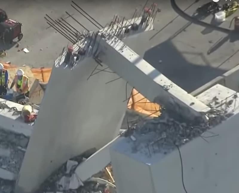
Top side of 12-canopy. NTSB:

Underside of 12-canopy. CBS: :

Top side of 12-canopy. NTSB:

jrs87 said:Best speculation so far. Very good.
Thanks, though again Alfie.Tx mentioned this earlier responding to an earlier post of mine (on top of all other preceding posts, including Ingenuity's thorough discussions of course!). At that time I thought an initial #11 crushing scenario seemed more plausible.
gwideman, Yes, I will be sure to recognize the input of others. Is the consensus now the PT rods and anchors in 11 did not fail, but rather the concrete or load distribution failed? Changing the PT rod tension moved compression/tension interface around near 11-12-deck in unforeseeable ways?
jrs87: Assume you mean "consensus"? I can only state my consensus with myself, which doesn't count for much, not being qualified in this field.
However, I am tempted to think that just by geometry, if the 12-canopy junction maintained its angle, that precludes the action starting with #11 shortening. But maybe concrete+steel is more flexible than I imagine.
As to why it happened during PT rod tensioning or detensioning, I don't have a comprehensive theory. For one thing we don't know where the PT end plates are.
We do know the lower tension rod was the one being adjusted, and it stayed with the deck. So if it was being tightened, then it would have increased the force pushing #11 out the end of the deck, I guess. Straw, camel, etc.
-
6
- #20
jrs87 got me thinking about why might tightening of the tension rod precipitate ejection of 11 and 12 from the end of the deck.
IF that occurred, here's a possible model:
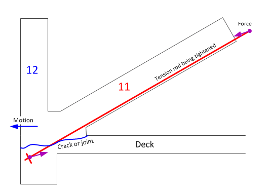
And we don't know whether they were performing an overall tensioning or de-tensioning operation, but as has been described earlier, even detensioning requires first some tensioning to loosen the nut. That small additional tension wouldn't explain why there's a crack in the first place, but it might explain why, given an existing crack or poor joint, the collapse occurred during the adjustment operation.
IF that occurred, here's a possible model:

And we don't know whether they were performing an overall tensioning or de-tensioning operation, but as has been described earlier, even detensioning requires first some tensioning to loosen the nut. That small additional tension wouldn't explain why there's a crack in the first place, but it might explain why, given an existing crack or poor joint, the collapse occurred during the adjustment operation.
- Status
- Not open for further replies.
Similar threads
- Replies
- 0
- Views
- 1K
- Question
- Replies
- 27
- Views
- 28K
- Replies
- 1
- Views
- 5K
- Replies
- 13
- Views
- 13K
- Replies
- 6
- Views
- 3K
