What's missing in the Toomas analysis are loads - I didn't ask him what numbers he used (he'd asked if I had centerlines at one point, but he soon sent the analysis), but may get back to him after I triple check mine (using new specs).
My question is why the stress is much different for #1/#2 and #11/#12 - is from asymmetric truss pattern, because #12 hangs off the deck, both, or ???. But he'd said 2D analysis wouldn't show this, and he's right - #1/#2 diag force shows ~40% higher than #11/#12 (they beefed up #1/2 but not #11/12). In final configuration, #1/2 would be floating on bearing pads (for expansion), while the pylon ends of main/backspans would be fixed, with some strengthening by being tied together and help from stabilizing pipes (but not as much as if this was a true suspension bridge).
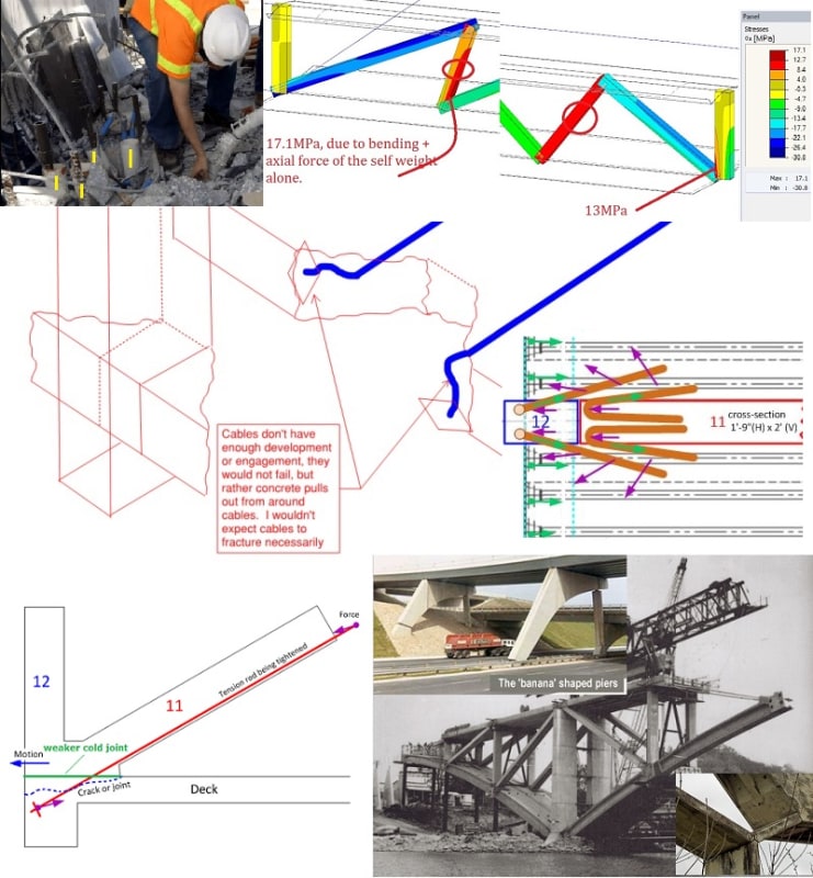
Would be good to analyze the strength of the #11/#12/deck connection (is simpler) - even within 10%. Estimated diagonal force is ~1350-1500 kips plus 560 kips PT tension (totals ~1400 kips horizontal) - the rebar is in the specs. This area has weak boundaries with the ~3" PVC pipes (two on each side of #12), rebar/other rods (which strengthens concrete, but would seem to create a "parallel sheer plane?", e.g. if many spaced 2" apart parallel to sheer force), and the ~8"/large drain pipe at the bottom through the diaphragm - plus the cold joint itself, which photos show had cracked. The #4 photo showed another hole near #11 in deck (that was later filled?).
Someone asked what may have happened to the rebar cage under #11/12. That's a good question (in the canal?) because the concrete was pulverized at the base of #11/#12 members, but may have held within the "cage". A chunk is missing from deck (seen in photo), but deck held the lower #11 PT rod. Photo shows the deck concrete broke apart at the east side of vertical PVC pipes as #11/#12 sheered.
Interesting how hpaircraft's idea above (9 May 01:08) is similar to gwideman IV 24 Mar 18 13:55. I can't find good photos that show if the #1/2/deck area had PVC pipes, etc.
I've noticed in a few concrete truss bridges (very limited knowledge) that the connections aren't rigid concrete - hinges, pivots, and steel were used (two of these expected soil shifting). The FIU span was only concrete and rebar - cracks showed after tensioning (adding 560 kips?) with support only on ends even before it was moved. As independent engineers noted, the connection should have been analyzed instead of just saying it 'looked okay', moving the span, and working over traffic. I'm curious how cracks changed after it was moved.