Eng-Tips is the largest engineering community on the Internet

Intelligent Work Forums for Engineering Professionals

  • Congratulations waross on being selected by the Tek-Tips community for having the most helpful posts in the forums last week. Way to Go!

Miami Pedestrian Bridge, Part VI 31

Status
Not open for further replies.
This might be a silly question, but:

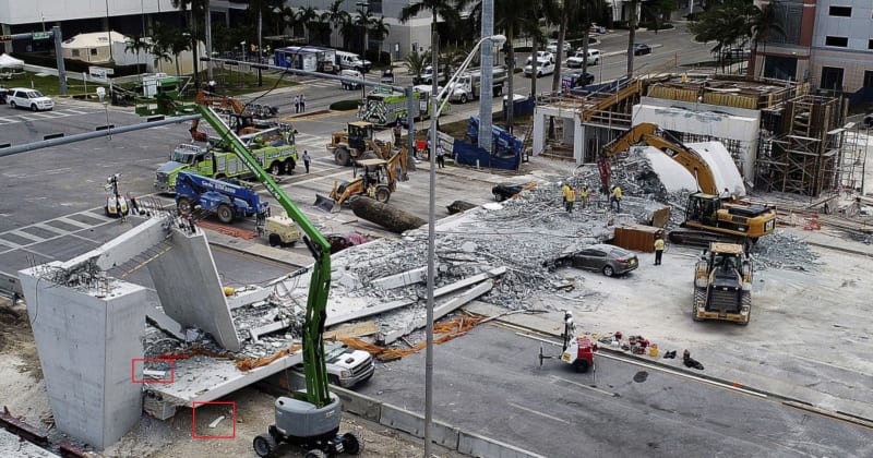
When I'm designing a fiberglass or carbon fiber structure, I tailor the local lamination schedule, particularly the fiber orientation, to accommodate local loads. Specifically, I use bias (usually +/-45-degree) fibers to distribute shear stresses into the rest of the structure. Based on that practice, I would have expected to see a set of angled "chevron" rebar reinforcements in the deck as shown below to distribute the thrust applied by #11 into the rest of the deck. The chevrons could go under or over the PT tendons, or maybe both.

20180508_174329_bl87en.jpg


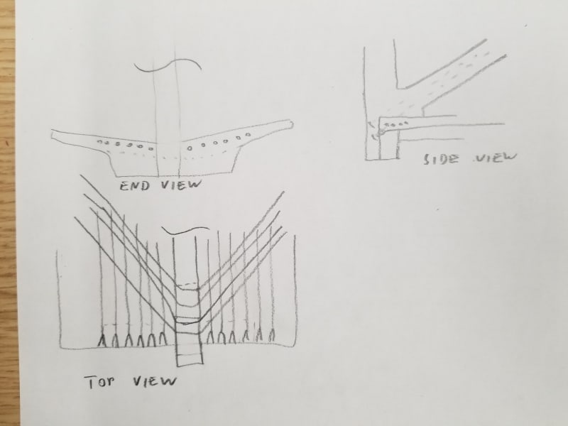
Would that have been an unworkable approach? The argument might be made that the deck is too shallow to accommodate these, but that might just be another way of saying the deck is too shallow to function properly.

--Bob K.
 
That's not a silly question, you are just thinking like a structural engineer should.
 
hokie66 (Structural)
The NTSB has been diligently doing the fact gathering. The Preliminary Report is being review, and might be released in 2 or 3 weeks provided no major concerns are found. Please remember that the Preliminary Report will only contain evidence, not conjecture nor speculation.
SFCharlie
 
I know that. Hopefully, the raw evidence will be helpful, but maybe not, without the analysis to follow. The fact of the embargo of evidence after the February date makes me think maybe there are some revelations.
 
Bearing shims. (uncropped photo, circled in red) Note one is broken and the other one ended up on deck.

bearing_shims_636569718048112339-Miami-bridge-collapse_pud5kl.jpg
 
Thanks for the diagrams. Is there one in plan or do we just assume that rectangular box of re-bar is only as wide as the no 11 column?

given that the 6507 bars are higher than the rather slim deck it would look like that to me.

I'm with hpaircraft here, but them I'm not a concrete structure person However, I would have anticipated either a significant end beam at 90 degrees to the column which is then essentially held in by the long PT rods in the base structure or something spreading the end column load more effectively into the lower slab structure as per the hpaircraft post.

It would be interesting to see where that cage of reinforcement ended up - in the deck or ripped apart

Any thoughts from the concrete structural experts?

Remember - More details = better answers
Also: If you get a response it's polite to respond to it.
 
hpaircraft said:
I would have expected to see a set of angled "chevron" rebar reinforcements in the deck as shown below to distribute the thrust applied by #11 into the rest of the deck.

Good post.

I too am not a concrete structure expert... hoping someone will chime in on your post, as it seems sensible.

What I'm still wondering (apologies to the group if this has already been answered elsewhere) is if that end thrust from the #11/#12 node was designed to be counteracted by the #1 and #2 node of the other half of the bridge, or if the two spans were intended to act with relative independence.

We haven't discussed the bottom node at #1/#2 much in our discussion so far.. on that end of the span, is there a shear lug or other feature which transfers thrust into the top of the column at that end, which differentiates it from the design used at #11/#12? Or is the span truly free floating at both ends as designed?

If the intent was that #11/#12 thrust would be counteracted by the other span, then not having any temporary method of bracing against that thrust seems like a massive oversight.
 
I don't have enough information, but, it may be that the loading from the web diagonals was not properly distributed into the deck... waiting for info... I'll then be able to see what failed catastrophically. The cracking observed may be related to the collapse.

Dik
 
hpaircaft is correct about the benefits of these chevron ties to bring back the compression effects of the tendonds to the location of the struts. Also, that can be accomplished by the reinforcing of the end diaphragm.

As somebody that have done this kind of things many times in concrete structures, I can tell you that typically you would put a big tendon in the same vertical plane of the struts to control the tension tie of the strut-and-tie system that happens that the node 11-12-deck. In this case it appears that the system relies on shear friction to transfer the tension transversally to the tendons. This is a akward way to do it, but it is possible to do it provided that you are careful and you have your forces correct, including any secondary effects. These effects can only be known if you do a tridimensional analysis. I wonder if only a plane frame analysis was done.

This is why it is important to get the signed and sealed calculations from FIGG. Although may be a brave soul out there can do the analysis and give us the forces in the node at the time of collapse using both methods.

But do not forget that node 11-10-canopy is also worthy of inspection.

However if the critical plane is that at the interface with the deck (or the canopy at below the canopy), the chevron ties are useless. Take a look at these planes and you will see that they do not have much rebar crossing them.

Good hunting

 
jgKRI,

I've been wondering that thought before (temporary single bridge versus final two bridges) but no way to find out so far.

It's not clear how the two bridges were going to be attached to each other, but there is a lot of spare re-bar floating around and possible connections to the pier.

I reality I don't think they would do it that way as it is not clear that the two structures would be tied together securely enough to allow forces to be balanced between the two structures.

The mad Spaniard I think hits the right note - to separate significant loads being generated into the deck and then having the tie rods which resist those loads not in the same plane on the face of it appears a little odd, though the nearest PT rod is fairly close.

Remember - More details = better answers
Also: If you get a response it's polite to respond to it.
 
The decorative 'cables' would tend to pull the two halves of the bridge together. The force on the abutment would be both vertical and horizontal.

Dik
 
I wonder if FIGG ever considered load testing the 174' span before transporting.

There are photos that show evidence of surface-mounted strain gauges on some diagonals, so some instrumentation was thought about. With FIU and its BSCE students/professors it could have been used as a research project.

It would have been relatively simple to load test, at least to part simulate the design vertical loading. It would have required some (significant?) temporary foundations to support the imposed test loads, but given the "pioneering" design, the cracking that occurred 10 days before transporting, and where we are now (collapse and loss of life), it may have been a prudent thing to do - granted, with 20/20 vision.
 
Ingenuity,
Figg may not have thought of that. Several of us here have suggested that they had a full scale prototype of this unique structure to test. Yes, they would have needed some footings at the ends. But the load test would have been simple, perhaps using sandbags or water bladders for load.
 
If we assume the available bridge construction as a three-plate girder, I would still expect some kind of lateral torsional buckling with large span length before attaching the tension cables. The upper compression plate has the small with, and the weight of the bridge is high since it is a concrete bridge. Additionally there is nothing to stop the end against rotation especially for the upper plate. I guess that the crash initiated with the buckling with the end rotation, and failed soon after.

The buckling might have been initiated by the application of tension in the cables cables one side only on the upper plate or unequal tension forces between cables located symmetrically. The failure occurred since there was not any balancing restraint at the end.

This are speculative guess-works only. I hope the final report will come out soon and give us better explanation about the failure.
 
Please read "The upper compression plate has the small width,...." instead of "The upper compression plate has the small with,..." in the my post.
 
I had a chance to see the video for the time of collapse, I saw that the last bay was acted as a mechanism.

I have two scenarios in my mind:

1. It seemed to me that the column-brace connection to the upper plate could not transfer the forces created, and sheared first, and the column (not the end column) pushed the lower plate and caused bending which probably was not designed for, and the entire bridge has collapsed. This requires a close up views/photos to understand the failure type at the connection mentioned here, and the reason.

2. There was not sufficient cable tension forces in the upper and lower plates to handle the forces created during the construction, and therefore the system acted as a mechanism at the weakest (or concentrated larges forces at this bay) location.

These may not be the case, but acting like a mechanism was clearly observed at the last bay. I hope the authorities can provide better explanation.

 
Ingenuity said:
I wonder if FIGG ever considered load testing the 174' span before transporting.

Not common unless included in the specifications... and, with design build this would not likely be included in the QA/QC... it's an added cost.

Dik
 
saplanti said:
I would still expect some kind of lateral torsional buckling with large span length before attaching the tension cables.

It failed because of ?, something beyond its inherent shape... an improperly designed tube could fare no better. It's not necessarily the shape. When I did the large freestanding stair at the Cornwall Centre in Regina, the contractor didn't want to remove the forming because he was afraid it wouldn't stand up.

Dik
 
dik,
I disagree that load testing of a new product is not common. This bridge was a completely new concept, not just a routine concrete structure. When I have done designs of building elements to be used as prototypes, I have required load testing.
 
Status
Not open for further replies.
Back
Top