Eng-Tips is the largest engineering community on the Internet

Intelligent Work Forums for Engineering Professionals

  • Congratulations waross on being selected by the Tek-Tips community for having the most helpful posts in the forums last week. Way to Go!

Miami Pedestrian Bridge, Part VI 31

Status
Not open for further replies.
Hi All,
I forget which PT video I was watching, but it showed putting a connector on the end of the PT rod, and then a short piece of rod to accommodate the ram. Oh yea, just like the excellent diagram above. The video showed a round tube on the end of the ram with a hole to loosen or tighten the nut.
SFCharlie
 
A little more about Sweetwater, it floods all the time, with just the least amount of rainfall. The easy flooding of Sweetwater (3ft above sea level)is in fact, preventing the USACE from pumping greater quantities of swamp water seaward to prevent coastal flooding in large portions of Miami Beach. Every storm drain in Sweetwater always has water just below the drain. One would think that any project in Sweetwater involving Federal funds would have some component of future proofing flooding. Miamians are greatly concerned about the ever increasing coastal flooding and while sea-level rise is always pushed to the front, it turns out large portions of Miami are sinking by -3mm/year. I'm surprised there isn't a telenovela about Miami-Dade politics. This bridge collapse is quite an eye opener.
 
With climate change and the rising of sealevel, Sweetwater could be inundated in a decade or so... Why would anyone develop in that environment?

Dik
 
Retiredat46... there will be lots of those... in particular any water treatment plants and sewers for a start...

Dik
 
Nasty looking cracks. Not sure exactly where those two photos were taken, but those are not off form finishes, which may indicate some attempt to repair or conceal has been done previously. Regardless of whether release of these photos was an accident by FIU, the newspaper is giving us information which the engineering community needed. The NTSB should get cracking with releasing the preliminary report.
 
When I looked at the long list of major bridge projects Figg has completed successfully, I asked myself why they even bothered with something like this. I'd like to know if Denney Pate made a special trip to Miami just to look at this bridge before the move, or if it was a brief side trip since he was already there for something more important. It's hard to imagine a minor project like this got his full attention at any time before the collapse.

From the MH article: "Outside experts have zeroed in on that truss member, identified in plans as No. 11..." The angle of the member suggests it's #11, too. It's just inches away from the area shown at the end of video 560.

Oh great...another signature bridge, this one for I395.

2018-05-08_0146_I395_q1y2tf.png
 
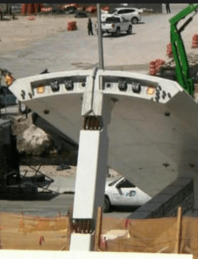
The photos in the Miami Herald are at the base of member 11. They are supposed to have been taken following the application of tension to the bars in member 11, and before the lift, which must have taken place after the white coating, which is not apparent in the cracks.

I think the photos support the theory that they thought that applying tension in the bars would pull the crack(s) closed without understanding they were levering the member off the deck instead. The part breaking off is not in the main load path of member 11 and shows what looks to me like lateral movement. There is little doubt in my mind that, if the cracks were caused by lateral slip induced by the tension bars, the additional load from the bridge installation would make that displacement greater, possibly by a lot, as the rebar between the members and the deck bent and the concrete it was embedded in gave way. Would their discussion then be about what the greatest load the bars could sustain in order to close the cracks?

I don't recall any evidence that there was a spotter at the base of member 11 to see that the crack was being closed.

A somewhat related article 
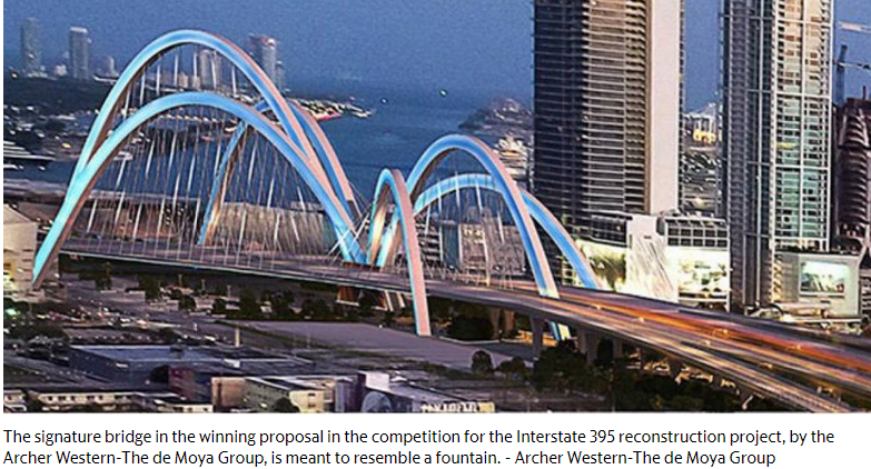
"The firms behind the failed FIU bridge give up the fight to rebuild I-395. So now what?"

Part of the reason they were fighting is they lost a bid, in part, because "the FAM team's bridge design violated one of the competition's rules because it included decorative elements that served no structural function. The FAM bridge, designed by FIGG and another subcontractor, featured two giant support pylons meant to resemble dancers that incorporated spinning discs at the top with no structural role."
 
A lot has been made of the joints at the ends of member 11. I agree that these joints had little hope of surviving, but I think focus on the stress bars and axial capacity of the diagonals is too narrow. To me, shortening of the top and bottom deck due to shrinkage and post-tensioning, resisted by the diagonals, made cracking at these joints inevitable.
 
hokie66,

If you are referring to my statement, it has nothing to do with axial capacity of #11 and only to do with the shear capacity between #11 and the deck.
 
It looks like someone made a vertical pencil mark across the larger crack so they could tell if got worse. The larger crack appears to turn horizontal to follow the joint with the deck toward #12.

Is there any way they could have added reinforcement around that area to save the bridge at that point in time?
 
To be fair to the Miami Herald, that (link by SF Charlie) is a pretty fair and accurate report for a non technical journal.

One question for those who are able to decipher the released drawings - Is there a clear picture of what the reinforcement looks like in the 11/12/deck interface?

What was actually connecting the compressive forces on no 11 to the lower deck? I've not seen in any of the drawings posted to date re-inforcement details that explain that.

Remember - More details = better answers
Also: If you get a response it's polite to respond to it.
 
3DDave,

I wasn't referring to your post. I agree with you, I think. Was just pointing out that axial shortening of the decks would be a big contributor to stress in the joints.

LittleInch,

From the information in the drawings, I doubt that I could draw details of exactly what was intended in that joint. The 8-#7 bars in the web member would seem to be woefully inadequate, no matter how they were developed into the deck. And I saw no indication of extra confinement reinforcement in addition to the column ties.
 
SFCharlie said:
We were wondering what the Miami Herald knew about the cracks. Well...
Cracks where FIU bridge buckled may have signaled 'imminent failure'

I sent the following eMail to the reporter of the article:

Since the NTSB has an embargo on information beyond February of this year, you might want to obtain copies of approved/reviewed reinforcing steel shop drawings; this would have occurred at an earlier date.

These drawings would show the location, placement and quantity of reinforcing steel in the 'truss'.

Great factual article, thanks,


Dik
 
LitleInch: "Is there a clear picture of what the reinforcement looks like in the 11/12/deck interface?"

I think the info is on sheets B39 and B40 which show up out of sequence in the group of drawings posted by jasm (Civil/Environmental)21 Apr 18 02:37. The areas of interest are:

The bottom of #11/#12
2018-05-08_1132___11__12_ahmnni.png


The section showing typical rebar placement
2018-05-08_1133__Section_B-B_ph3cxb.png


If you step through this time lapse video from 35 seconds to 1:35, you can see the form work for the truss was in place before the deck was poured. That makes me wonder if there really was a cold joint between the deck and truss members. I couldn't tell for sure from the video. Maybe you can.
 
This has better detail from above referenced doc page 86/110 B-61 comparing #1/2 to #11/12. There seemed to be more rebar in collapse photos than in #11/12 here - I looked for it elsewhere in prints but didn't see it... like what's sticking out the bottom of #12 where it's resting on top of pier.

On page 64/110 B-39, note 8 says "Secondary pour shall take place 180 days after casting of main span". Pour sequence elsewhere said 1) Deck, 2) members, 3) canopy, so I wondered if this meant 180 days between deck and members being poured (probably a dumb question, but time lapse messed up my perception).
new-truss_detail-N_and_S_r0hwpg.jpg
 
Thanks for the better detail.

I think Note 8 goes along with Note 7, and only applies to the concrete for the hinge locations. I remember seeing pictures after the collapse that showed the hinge locations hadn't been filled yet. They had slings through the gaps.

2018-05-08_1224_Notes_7_and_8_nrywta.png


2018-05-08_1246_hinges_kcefii.png
 
Status
Not open for further replies.
Back
Top