Eng-Tips is the largest engineering community on the Internet

Intelligent Work Forums for Engineering Professionals

Miami Pedestrian Bridge, Part VII 51

Status
Not open for further replies.

JAE

Structural
Jun 27, 2000
15,432
0
36
US
A continuation of our discussion of this failure. Best to read the other threads first.

Part I
thread815-436595
Part II
thread815-436699
Part III
thread815-436802
Part IV
thread815-436924
Part V
thread815-437029
Part VI
thread815-438451


Check out Eng-Tips Forum's Policies here:
faq731-376
 
Replies continue below

Recommended for you

Ingenuity (Structural) said:
Give me a break - the name and title of "interior designer" is protected too!

The referenced Miami Signature Bridge Project is a $800 million project, not a living room remodel, where someone seems to be holding herself out as an architect. At best, it is inappropriate. It demonstrates an ignorance of the professional licensing requirements that someone running an engineering business should be familiar with.


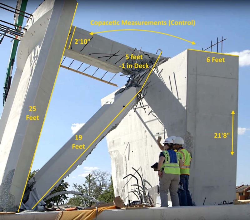
I am wrong about the top of #11 missing more section than the base. What is somewhat interesting is that the remaining north portion of the canopy is longer than the distance from the end of the canopy to the front of the #10/11 blister. The distance from the end of the canopy to the beginning of the blister is 21'-10", while the remaining north section of the canopy is approx. 25 ft.

Watching the Dash Cam video, #10 maintains its top & base geometry in relation to the south portion of the bridge as it falls. This cannot be said of #11. The #10/11 node is positioned south of the center of the #10/11 blister. The canopy breaks directly in front and around the sides of the blister. There is obvious rotation of #11 around the #10/11 node. It is not as easy to gauge the rotation of #11 at its base, in relation to the deck.

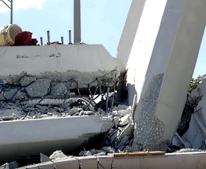
There is very little damage to the diaphragm. Even the recess between the PVC pipes is less than a foot deep. In the photo of the NTSB staff examining the PT bar they are all standing atop the rubble strewn deck.

While there is no explanation as to why, it is possible that #11 buckled under the #10/11 node & the very stout & grouted #10/w node & @95% of the bridge mass attached, hammer #11 rupturing the base (allowing both ends to rotate) and sending #12 sliding off the back of the diaphragm. The sliding of #12 accelerates the rotation of the #12/canopy section while the base of #12 traps the bottom of #11, at which point the diaphragm is yanked off the pylon and the lower PT bar is disemboweled from the trapped #11 truss.

The problem I have with this scenario is that it would seem that both PT bar should have extended somewhat beyond the blister.

Close_Up_a1_jt94vr.jpg


Close_Up_2_cbduqg.jpg
 
Ronbert said:
In all of the states (12) I was registered in (retired) the President of an engineering/architect firm had to be registered.

Had to be registered or were registered? As a matter of course, they may have been registered, but, it may not have been as association requirement that they had to be. JAE notes that it appears that they had to be, but in reality, they only needed signing authority. I think it's a good idea that they are...

Dik
 
epoxybot said:
There is very little damage to the diaphragm.

Almost like there was insufficient attachment, perhaps. I would be surprised if buckling happened at a node... perhaps 'crushing'.

Dik
 
Concrete can have some ductility and you can have 'breakage' and still maintain some strength. The collapse was sudden, and, I would suggest that the failure was the same...

Dik
 

dik (Structural)
13 Jun 18 14:06
Concrete can have some ductility and you can have 'breakage' and still maintain some strength. The collapse was sudden, and, I would suggest that the failure was the same...

Dik

In the concrete and masonry seismic survivability world, we did some tests to evaluate your statement. There is some post-fracture life left, but the tail is very short. Grinding and crunching is still absorbing some post-fracture energy, but cannot be relied upon. Embedded ductile reinforcement or ductile material overwraps usually disguise post-fracture energy absorption capability of the masonry or bare concrete.

--CCW1
 
dik said:
Almost like there was insufficient attachment, perhaps.

The deck reinforcing was placed, the truss forms set & #11 rebar cage set, followed by #12. So how does the #11/12 node rebar fit unless it is spliced?

61651_exktkr.jpg
 
CCW: I've seen heavily double reinforced sections go through serious rotations and still maintain a substantial part of their strength.

Dik
 
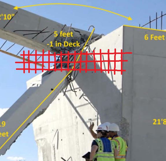
This photograph says it all. The bottom of #11 should have been tied into the deck with a massive amount of steel in the form of a load spreader beam, as indicated in red in the image below. Only problem, is that the shear stress at this point was so high that not enough steel could have been provided to satisfy the code requirement. It is quite evident that the person who designed this bridge did not have even a rudimentary grasp of the flow of forces through the structure, nor of how to cater for those forces through the imposition of structural elements.

Spreader_Beam2_u0csmy.jpg
 
FIU had grand plans for 'signature' bridge. But the design had a key mistake, experts say...


That resulted in a support piece that was likely not thick enough, and even more significantly, lacked sufficient steel rebar reinforcements at the point where it connected to the deck, all three engineers who reviewed the calculations said. That meant it could not adequately withstand the load of the bridge weight it was meant to carry, nor resist "shearing" stress at the connection to the deck that tended to pull the base of the diagonal strut from its anchor, they said.
 
I like that Miami Herald report. Not often these days do I praise the press, but they have done their job in this case. And I have learned a new structural term..."undernourished" to describe an inadequate connection.

Will have to read it more thoroughly later, but think they haven gotten the gist of the problem.
 
Miami Herald said:
But the three outside engineers who studied the plan in detail said someone should have caught an error that Beck and Howell characterized as clear.

Miami Herald said:
This is not a big project," Beck said. "It’s a darn pedestrian bridge.

Notwithstanding the other complicating factors such as ABC, the titanium concrete mix, etc., the authors of this article are stating that an engineer's opinion is that the root cause of this failure is an obvious error.

That brings up a question for the engineers that specialize in this design area. Is the error really that clear? Do the engineers quoted in this article have access to additional information?


But, it did withstand those forces for hours, days, etc. after being set in place on the pylons or piers.

The off-design event that resulted in taking it down was horsing on the two PT rods in #11 to attempt to close cracks that had appeared earlier and was noted in the EoR's prior phone call. The attempt to close cracks by retensioning PT rods in #11 was a committee decision that was an error (In My Opinion). The force vectors from #10 and #11 cross under the blister, form an "X" under the blister and induce a couple into the blister with resulting punching loads off the north and south ends of the blister. The large change in cross-section from relative thin canopy thickness, to the thick blister cross-section causes large stress concentrations at the local junctions from the couple at the change in cross-section. (IMO).
 
Miami Herald said:
Beck said the concrete at the point where the bridge failed shattered into unusually small pieces, suggesting it was highly brittle, though he can't say whether that had anything to with the collapse.
I didn't know if this was typical, but noticed the small pieces, as if an "explosion" occurred... also small pieces in the rubble where #9 punched through the canopy. Still wondering why ~5 ft is missing from #11 with rebar/PT rod/duct and PVC pipes still intact.

As discussed here, the engineers for Miami Herald focused on the weak connection.
Had been looking at I-35W connection failure. I wouldn't think there was much design emphasis on the #11/12/deck connection - they should have taken another look at numbers after cracks appeared and seen something was wrong.

Description/computer model of bridge. Animated failure starts at 4:00. Curious if they can do similar with FIU/exploding concrete.

Partial report from NTSB - they wanted to see calculations for gusset plates, but couldn't
(MH article said engineers reviewed nearly 2000 pages of calculations - wonder if any for the #11/12 connection)

They have a memorial of the failed I/35W gusset plate (kinda cool..). Just a piece - these were 6' by 9'
 
To answer your question, bimr, the engineers quoted by the Miami Herald did have additional information. The article stated that they had the calculations, which were obtained through a freedom of information request.
 
I don't concur with their comment about the irregular shaped web... this feature would have made me go into 'overdrive' because of the irregular nature of it. As they say, "Familiarity breeds..."

Dik
 

hokie66 (Structural) said:
To answer your question, bimr, the engineers quoted by the Miami Herald did have additional information. The article stated that they had the calculations, which were obtained through a freedom of information request.

hokie66, you have said from the beginning that it was a problem with the connections. Is that "clear" from just a cursory look at the design drawings?
 
Status
Not open for further replies.
Back
Top