chris snyder,
Reading thru your most recent post it's amazing how much of this thread I've already forgotten.
I've never done any forensic engineering before. It feels odd, as if I'm tailoring my answer to fit the observations. Kind of like having the answers to a test before you take it. But maybe that's what forensic engineering is.
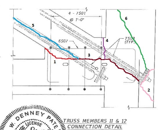
Here's a possible sequence of events at joint 11-12 based on observed cracks, and the little we know, borrowing heavily from earlier posts. Cracks noted sequentially by numbers. It's a good story. Whether it bears any resemblance to reality is an open question:
1) Observed crack prior to move, a result of dead load. Story should have ended here. Remedial action should have been taken (if possible?), or bridge destroyed and begun anew. Maybe stressing of temporary PT in 11 partially closed crack; maybe it did nothing other than give a false sense of security.
2) Move occurred. PT rods destressed. Crack reappeared. Temporary PT in 11 was now called on to close crack and save bridge. Assume both PT rods are stressed, possibly above what was done in 1. Tensile cracks may begin to appear behind top PT bar anchor plate.
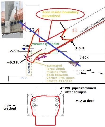
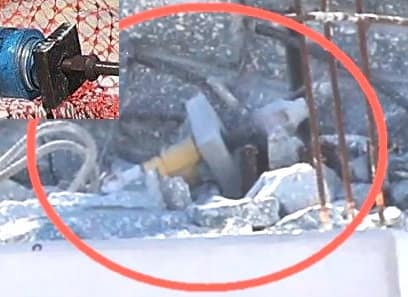
3) With no dedicated confinement steel in front of anchor plates tensile forces acting perpendicular to the PT rods cause crack to propagate. Dead load also continues to work on crack. Shape and depth of crack beneath 11-12 indeterminate. Two things conspire to separate the top PT anchorage from the slab. Shear force from 11 now pushes horizontally against top rod, and PT force acting on top anchor plate will initially want to pull it upwards. Pictures show a very neat cavity between the nearly undamaged PVC pipes on either side of 12 within the diaphragm, possibly the result of top anchor plate bursting, or shear, or a combination, so crack at deck surface would fall inside of PVC pipes. Stress in top PT bar now goes to zero. Axial load in 11 now generates shear failure along this 1-2-3 plane. This begins collapse sequence. More on this below.
4) Slight movement along 1-2-3 plane causes load redistribution, resulting in hinging at various locations. Hinge points are top canopy, bottom of 11, top of 11, bottom slab, and even base of 12, with the order possibly being as noted. With the tremendous loads acting here, there's no reason to believe 11 would remain attached to 12 for long.
5) Bottom PT rod is torn out as 11 rotates and slides out.
6) Face of 12 is ground away, partially from 11, and partially as it slides downwards and outwards along back edge of diaphragm, once bridge has fallen far enough for 11 to push it beyond diaphragm.
Questions:
--What is the horizontal movement necessary along the 1-2-3 plane before collapse sequence and hinging is initiated? mm or cm? Because bottom PT bar remains attached to slab we're probably only talking mm's.
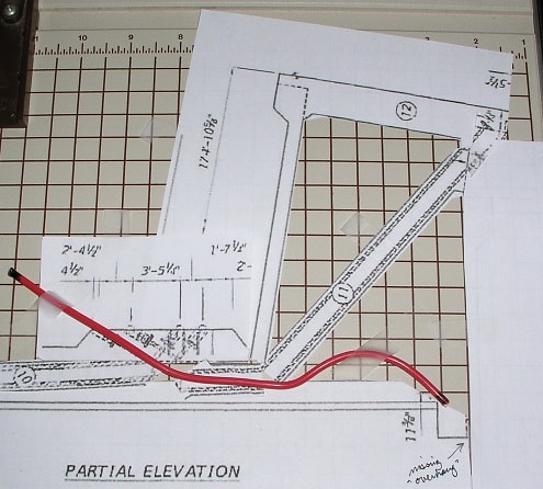
--Why does bottom PT rod remain in slab? It's sort of obvious when looking at the picture, but still unsure.
--Neither mild steel chevrons placed in deck slab, nor placing longitudinal PT along the centerline of bridge, would have likely prevented this potential failure mechanism from happening as crack 3 could also progress along top of slab to near top anchor plate. Plausible?