Continue to Site

Eng-Tips is the largest engineering community on the Internet

Intelligent Work Forums for Engineering Professionals

  • Congratulations KootK on being selected by the Eng-Tips community for having the most helpful posts in the forums last week. Way to Go!

Miami Pedestrian Bridge, Part X 50

Status
Not open for further replies.

JAE

Structural
Jun 27, 2000
15,444
A continuation of our discussion of this failure. Best to read the other threads first to avoid rehashing things already discussed.

Part I
thread815-436595

Part II
thread815-436699

Part III
thread815-436802

Part IV
thread815-436924

Part V
thread815-437029

Part VI
thread815-438451

Part VII
thread815-438966

Part VIII
thread815-440072

Part IX
thread815-451175


Check out Eng-Tips Forum's Policies here:
faq731-376
 
Replies continue below

Recommended for you

Yes if you conceive of it as strut and tie there is an obvious lack of tensile development back into the deck. Diaphragm II needed to be a lot chunkier (or otherwise stronger, eg a steel plate), and needed to tie back into the deck.
 
Vance Wiley (Structural) said:
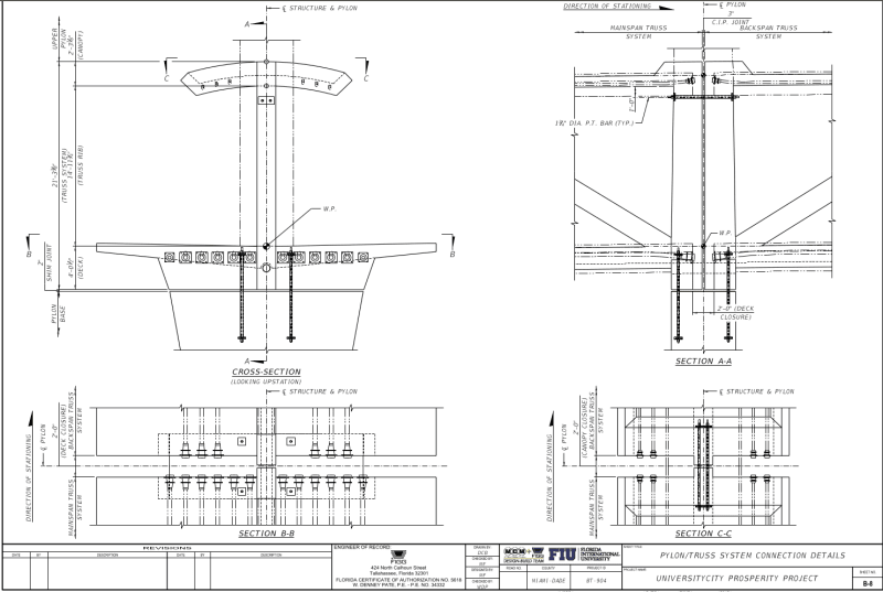
Could someone identify the elements/parts in the closure strip over the Pylon which will provide 2000 kips of tension tie between the north and main spans?

Screenshot_from_2019-06-19_15-06-31_fsa8qd.png


The above drawing shows the two spans would be eventually bolted together horizontally just below the roof. Each span also has its set of holding down bolts firmly fixed to the piers.
 
I believe there are also a couple of post tension cables as shown in Section C-C to tie the canopy portions together.
 
These are the old drawings as the "holding down bolts" moved right next to member 12.

Also these bolts are pretty puny - barely 1" diam with not much bearing surface. If this bridge wanted to do anything / move anywhere those bolts are not going to hold it together, especially when the bolts are at canopy level and the forces at deck level.

And there is a 3" "CIP" joint. That doesn't sound like a great idea.

Remember - More details = better answers
Also: If you get a response it's polite to respond to it.
 
saikee119 said:
,3DDave, & LittleInch
Thank you - that is about what I found - and I do not see anything that could come close to 2000 kips capacity there.
I am haunted by the suspicion that the designers thought the fake pipe stays were working components with the weight of the structure on them and the horizontal components of their tension forces would pull these two bridge spans together over the pylon with enough force to contain any blowout.
Of course that concept overlooks the period when the main span must support its own weight until the back span is complete.
Maybe that was just the best story they could conjure in a hurry.
No getting around the fact that everyone was watching an actual catastrophic failure in progress. Not many get to observe that.

 
Made a new Playlist for DROPBOX video clips, and moved the short drone clips of the pylon drain into it. Here are the links to all Playlists, for handy reference:

Synopsis of DROPBOX clips:

Just after the Pylon-end SPMTs have put one wheel on the center median, the move stops and people congregate at the pylon end and appear to be look up at the drain area. It's also possible it was just warmer over by the canal, or people were drawn like moths to the brightly lit Pylon end. This SPMT stop coincides with the 0:54 mark in the Move Part 2 - ground view video, and it should be noted that the ground view video also shows people milling about in the area of the spotlight, and many are taking "tourist" pictures, so it could just be a nice place to save a memento.
At 0:56 of the second video a guy in a white hat comes into view from beneath the deck corner, and he's in the classic chin-in-hand, elbow-on-hand contemplation pose. Not a good sign.

At the same time as the gawkers 2 video above, a crowd of people surrounds a person holding a large tablet. My guess is that this is the VSL crew.

A different perspective of Deck activity (starting at 1:38 mark) that occured during the "Pause" that ended the Move Part 2.

These are previously posted clips of a drone view of the Pylon drain showing what appears to be a crack radiating from the upper RH rim edge of the drain up to the right (west) side of the Column 12 base.

East side ground views of the last stages of Move Part 3, focusing on the SPMTs.


BONUS: here are some direct links to a few of the DROPBOX vids:

COMMENT: If the cribbing is topped with low-friction plastic pads, this would explain the slip-and-slide motion of the deck observed from ground level as the SPMT traversed the center median. Is it really a wise choice to chain the canopy to the SPMT tower arms while the deck rests on slippery cribbing on the tower tops?

 
Vance said:
Thank you - that is about what I found - and I do not see anything that could come close to 2000 kips capacity there.

Doesn’t look like a very serious connection. I assumed from FIGGs comments about the permanent condition reducing loads on member 11 that it was going to connected to make it continuous. Maybe I misunderstood what they meant.

Vance said:
I am haunted by the suspicion that the designers thought the fake pipe stays were working components with the weight of the structure on them

I’m sure they knew they were decorative.
 
Here's another thought experiment.

Take a 6" diameter cylinder, place 1% vertical reinforcement, 8-W3.5 wires, you would need to use W4 wire if you want them commonly available deformed, cast the first half with a cold joint at 30 degrees to vertical, (not an exact match, but close, plus I have the sine and cosine memorized), wait a few weeks, cast the second half, wait a few more weeks and then test in compression.

How many ties would you need to have to get the cylinder back to the strength of a cylinder that was cast monolithically without any reinforcement?

Probably even worse for a nearly square rectangle.
 
Tomfh said:
Maybe I misunderstood what they meant.
I think you have it exactly correct. But from what we can see there was not yet anything detailed to provide that tie. Maybe that was something FIGG was going to add (if they had time). Maybe that was what was referenced in the text to the home office as "additional ideas to better the current situations".


hpl575 (Structural) said:
How many ties would you need to have to get the cylinder back to the strength of a cylinder that was cast monolithically without any reinforcement?

The concrete did not failed by pure compression in the bridge. The horizontal component of the axial thrust of Member 11 was likely the driving force to shear the 12/11 outward once it found the weakest plane along the construction joint at the top of the deck.

Apart from the 8" pipe sleeve cast horizontally below the deck there were 4 vertical duct sleeves, about 4" diameter, cast on either side of Member 12. These cast-in items would have no problem to provide a path of least resistance against horizontal shear against the Member 11. OSHA report's photos have shown the concrete has separated from the vertical ducts possibly by about 5mm or 1/4".

The Member 12 rebar left after failure has indicated the concrete was not successfully gripping the steel to realize the steel's maximum material strength. Thus the rebar development length and its close proximity to external surfaces were also problematic.
 
As facts have began to come forward, I am interested in what others opinions may be for Code changes.

A few that I have come up, just my opinion, and not all the facts are in.

For ABC or any method of construction that puts the general public at risk, are Construction Phase load factors and combinations applicable? Should the load factors and combinations for permanent structures be used? I would admit that realistic construction live loads may still be applicable. A dead load factor of 1.1 and phi of 0.9 shown in the presentation, really. Especially for a structure when you don't fully understand what is going on. For ACI 318 1.4D with phi of 0.75 for shear would to me produce a much more reasonable factor of safety for a structure that is putting the public at risk. This would have also given lots of head room for live to meet the 1.2D + 1.6L for a structure this large.

Should non-reductant and highly critical members be detailed more like the details for high seismic risk?

A better definition of how and when the shear friction can be used with the applicable limitations.

Not actually code but similar.

Peer reviewer hired by the design team, this would seem to me better served if the peer reviewer was a direct agent of the Owner. I have a similar opinion when testing agencies work for the Contractor rather than the Owner.

 
I believe the construction loads would have been applied with the corresponding safety factors according to the design code.

During construction the loads are short term and so a lower level of safety factors are commonly accepted.

The shear friction isn't an additional requirement but a method to work out or explain what could be the worst case. It is a distraction from the root cause of failure here in my view as the 11/12 did not have any fixing to be torqued tight to the deck to prevent one surface move relative to another.


hpl575 said:
cast the first half with a cold joint at 30 degrees to vertical
You have described conditions similar to the test for epoxy injection of cracks in concrete. As I recall, specimens of concrete were sawn at an angle, held in position with appropriate clearance, and injected, allowed to cure, and tested as you describe. Because this test was for the epoxy repair, no reinforcing was considered. But the concept of the test you describe is being used.
I would say YES. Particularly with no redundancy. I previously posed the question "How do you compensate for a non-redundant bad idea? Maybe with another bad idea?" That would remove the non-reduntant condition, but it might not solve the "bad idea" part.
Not with the public exposed to a corresponding risk. OSHA will have to decide how to protect the construction personnel. NTSB will likely have pointed comments also.
 
Vance said:
Maybe that was something FIGG was going to add (if they had time). Maybe that was what was referenced in the text to the home office as "additional ideas to better the current situations".

That makes sense.
 
It this the correct book to study in regards to this accident?

51S8o71Ms-L._SX375_BO1_204_203_200__lpyzrc.jpg
 
MikeW7, Farmers.. Amen to that!

Edit: P.S. No fair, the farmer in above video link is an Auburn University engineering graduate! LOL
 
Status
Not open for further replies.

Part and Inventory Search

Sponsor