Eng-Tips is the largest engineering community on the Internet

Intelligent Work Forums for Engineering Professionals

  • Congratulations waross on being selected by the Tek-Tips community for having the most helpful posts in the forums last week. Way to Go!

Miami Pedestrian Bridge, Part X 50

Status
Not open for further replies.

JAE

Structural
Jun 27, 2000
15,432
0
36
US
A continuation of our discussion of this failure. Best to read the other threads first to avoid rehashing things already discussed.

Part I
thread815-436595

Part II
thread815-436699

Part III
thread815-436802

Part IV
thread815-436924

Part V
thread815-437029

Part VI
thread815-438451

Part VII
thread815-438966

Part VIII
thread815-440072

Part IX
thread815-451175


Check out Eng-Tips Forum's Policies here:
faq731-376
 
Replies continue below

Recommended for you

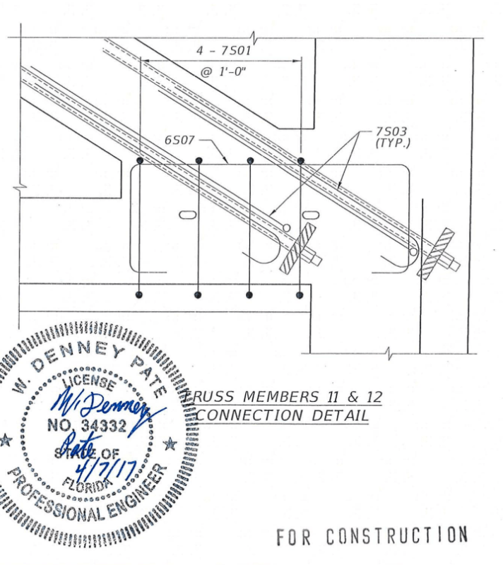
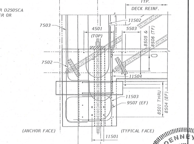
Consider a vertical pinned end ideal truss, all members including the top and bottom chord are pinned at the joints. Now enforce an outward horizontal deflection at the first interior top node. The truss simply performs a rigid body rotation about the end pin support. Suppose now that the chords are continuous and extremely rigid in shear and flexure and cannot displace vertically. What happens when the first interior top is moved horizontally but cannot move vertically due to the rigidity of the chords, the diagonals will become axially loaded, in the case of Member 11, compression.

No truss is perfectly one or the other, although many, many years ago steel trusses were built with all "pinned" end members. Trusses with continuous top and/or bottom chords will induce axially loads into the diagonal members if one chord or the other is lengthened or shortened due of differential thermal movements or volumetric changes. This is also true for trusses if both top and bottom chords undergo the same change and both end supports are restrained from horizontal movement. Generally, these effects are not much of a factor for a metal truss, but still something that needs to be checked in final design if these conditions can be produced.

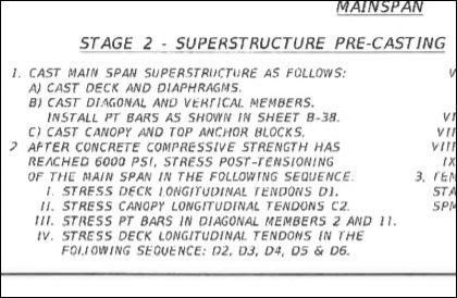
For a top concrete flange approximately 1 foot thick and 18' wide including edge upturns, 18 square feet, that has 4 tendon ducts with 12 strands each, total of 48, stressed, you will get 2.667 strands per square foot of concrete. The top flange is also cast in an arc that increases it's flexural rigidity. For the bottom chord approximately 1.5 foot thick average and 32' wide with upturns, 48 square feet, that has 10 ducts of 19 strands and two ducts of 12 for a total of 214 strands, the bottom chord has 4.458 strands per square foot of concrete. The bottom chord has approximately 1.67 times the prestress stress as the top chord and would be expected to have more total concrete creep shortening over time. Shrinkage also comes into play, bottom chord gets a head start but has a higher V/S than top chord slowing bottom chord shrinkage relative to top chord. Some say Hoover Dam is still shrinking. Very simplified analysis I'll admit.

In the spring temperatures trend warmer, bridge gets warmer, bridge gets longer, any amount of horizontal restraint at the supports increases compression in Member 11. Thermal mass of top chord is less than bottom chord, heats up faster as ambient temperatures rise. Top is always in sun, bottom chord get partially shaded from top chord, I'll give nearly white concrete better than medium gray for this effect. The thermal effects are still transient as long as everything remains elastic.

If, and this is the big if for which much more data needs to be made available, the structure has now reached the point were some of the steel elements are yielding from the combination dead load, creep, shrinkage and ambient temperature increase effects, then increased crack widths would be expected as these parameters continue to increase. If the steel is yielding, then differential temperatures with top warming faster than the bottom and then eventually equalizing would also "walk the stress strain curve to the right", eg for perfect elastic plastic curve if total is 0.1 inches at peak, 0.05 elastic and 0.05 plastic, then each cycle moves 0.1 inch but only recovers 0.05, then each cycle move the curve to the right 0.05 inches.

As a side note, creep due to prestress and thermal shrinkage due to cold are the nemesis of anyone one who has ever designed a posttensioned parking garage on my region. I have yet to find one that has internal ramps that didn't have at least diagonal cracks in the columns, especially at the short column segments between a ramp and flat floor. The closest I ever came was a single supported level garage that higher than typical column heights and an external, structurally isolated, ramp.
 
jrs_87 (Mechanical), Tomfh (Structural) & Sym P. le (Mechanical),

Screenshot_from_2019-06-22_01-54-59_eownf4.png

Screenshot_from_2019-06-22_01-57-00_oia8hz.png


The horizontal bar above the lower PT rod makes me think it is bar mark 7501. Thus the shearing plane may be above the 4x7501 rebar since a failure occurs at the plane of the least resistance. We probably need more photos to confirm but the first 7501 is visible in Fig 67 (clearest), 65, 64, 63, 60 and 58 of the OSHA report.


Correction

Found the deck debar drawing depicted below

Screenshot_from_2019-06-22_12-26-09_dprnxy.png


The horizontal bar in the photo should be from the typical deck reinforcement (5S01).
 
I think the cold joint under the south part of contact between 11 and 12 and the deck had failed during earlier stressing in the form or under other support conditions. The strain on this joint caused by deck stressing could be the early movement.
The joint was not intentionally roughened and the break was quite clean across the deck. Member 11 seems to have simply slid across the deck.
 
Vance Wiley (Structural),

OSHA report mentioned "There were a number of rebar crossing the construction joint, but not all bars could be considered for shear transfer because of lack of development length. Industry standard requires that “shear friction reinforcement shall be appropriately placed along the shear plane and shall be anchored to develop fy on both sides by embedment, hooks or welding to special devices.” This criteria excluded some of the rebar crossing the construction joint."

It is possible some bars, including the L and J bars were too short and too close the shearing planes. When the 11/12 was separated from the span concrete around the bars not having adequate development (too short above the boundary of failure) could be grounded and disintegrated resulting the failure resembles a blow out.
 
Vance Wiley said:
I find it interesting that the concrete around the J-Bars is simply gone. Hit them with a garden hose and use them again. No evidence of stress to the bars.
Where is the concrete? It looks like the concrete blew out like a hand grenade.(Maybe it was terrorists?)
If this is the way 8500 psi Titanium DiOxide concrete works there needs to be a LOT of confinement reinforcing used.
Please comment - I think this is gonna prove critical in this case. Does anyone have experience with concrete and aggregates like this? Is it common in FDOT structures?
Thanks,

I find it interesting as well. It is one of the least predictable aspects of the failure. I suspect the concrete failed without too much deformation of the bars since the upper longitudinal bars were in compression and terminated above the shear plane. The J pushes into the block of concrete and causes a concentrated splitting force near the outside face of 12. The high strength concrete tends to splinter more.
 
Vance Wiley said:
Member 11 seems to have simply slid across the deck

Playing devils advocate here, the simply sliding argument doesn't hold water. For that to occur, it had to go somewhere and it couldn't. It was constrained by the lower PT bar and 12. To say that it slid is to say that something ruptured, eliminating the need for sliding. The video seems to indicate that 12 held its ground initially in the collapse sequence. If the argument is that 11 slid in conjunction with 12, that would require the canopy to hinge also. This is a static impasse.

This leads me to believe that the initial failure was a blow out of 11. Perhaps the bottom end blew out and the PT bar sleeve was a guide for it to follow as it continued to crush. As I said earlier, it seems that 12 was brought down by the canopy, but that doesn't mean that a good portion of the node didn't crumbled in an initial rupture with 11.

saikee119 said:
The horizontal bar above the lower PT rod makes me think it is bar mark 7501

Figure 60 (OSHA) shows that the separation is at or just below the deck. I think this eliminates the possibility of it being rebar intended for the above slab block. I haven't found the rebar drawing for the deck, at least not one that I'm any good at reading.

 
jrs 87 said:
Anyone care to help refine this? I have not yet reconciled deck level with PT bar and rebar position.

You should draw the green line going around the back side of the plate (the plate stayed with the deck). It looks like the shear plan dips down a bit too quickly behind the plate.
 
It seems to be confusion that 12 could stop the movement of 11. I have always in my mind the two moved as one entity, at least when it started. The doomed bridge was a bad design because there is so little concrete to prevent 11/12 from kicking out.

For elegance the 11/12 was not thickened to make the joint stronger especially it was stressed abruptly relative to the deck. The five pipe and sleeves at the failed location have definitely weakened the joint but I bet my money on none of them being considered in the actual structural calculation.
 
saikee said:
The doomed bridge was a bad design because there is so little concrete to prevent 11/12 from kicking out.

Agree. It largely boils down to the flimsy diaphragm at the end. It's akin to punching shear failure in a slab that's too thin. Diaphragm II shoulda been a lot thicker, or alternatively needed something akin to a shear head to provide steel across the potential cracks.

And yes the penos made things worse. It still didn't work though without the penos. It was failing under dead load. Imagine how it would have gone under ultimate dead and live combination.
 
I should have been a bit more precise in my statement "simply slid across the deck" - obviously that applies to a limited part of the node 11/12 junction with the deck. The initial cracking (from stressing the deck or from shrinkage?) defeated any cohesion and provided the initial indication of a problem. But the very limited damage to the deck surface at the southerly portion of the contact area confirms the lower PT rod was the only thing that provided significant resistance to sliding in this area.
It will be telling if the upper part of the 4 #7 hoops which were intended to mobilize "shear Friction" can be examined to confirm the statement that they actually failed in shear.
Regarding the statement by OSHA that the PT rod "sheared" - I do not buy that a bit. While watching the NTSB pics of people standing around the bent PY rod in its sheathe, I often thought "if that rod snaps someone is going to lose an arm - or worse". In viewing the photo of the supposedly sheared surface of the PT rod, there is no concrete over that "sheared surface" which would sustain the bend in the rod that we see in the NTSB pics of their on-side data gathering. As I see the end of the PT rod in the deck segment, it appears to have been cut with a gas torch. Can anyone comment on this?
I view the construction and (assumed) design intent of the node 11/12 as a block on the deck with member 11 attached and pushing downward and north and 12 simply setting on top of that block with relatively low (compared to 11) load. Without specifically being reinforced for the tear-out, the portion of deck under 12 had little or nothing to contribute to the stability of this joint.
And the way the concrete shattered and 11 was splitting longitudinally, there may have been severe rupturing - but it retained the capability to push the entire block out of the end of the deck. Which probably means the block/node punch out failure preceded any significant failure in 11 above the node.

 
Vance Wiley said:
I should have been a bit more precise in my statement "simply slid across the deck" - obviously that applies to a limited part of the node 11/12 junction with the deck. The initial cracking (from stressing the deck or from shrinkage?) defeated any cohesion and provided the initial indication of a problem. But the very limited damage to the deck surface at the southerly portion of the contact area confirms the lower PT rod was the only thing that provided significant resistance to sliding in this area.
It will be telling if the upper part of the 4 #7 hoops which were intended to mobilize "shear Friction" can be examined to confirm the statement that they actually failed in shear.
Regarding the statement by OSHA that the PT rod "sheared" - I do not buy that a bit. While watching the NTSB pics of people standing around the bent PY rod in its sheathe, I often thought "if that rod snaps someone is going to lose an arm - or worse". In viewing the photo of the supposedly sheared surface of the PT rod, there is no concrete over that "sheared surface" which would sustain the bend in the rod that we see in the NTSB pics of their on-side data gathering. As I see the end of the PT rod in the deck segment, it appears to have been cut with a gas torch. Can anyone comment on this?
I view the construction and (assumed) design intent of the node 11/12 as a block on the deck with member 11 attached and pushing downward and north and 12 simply setting on top of that block with relatively low (compared to 11) load. Without specifically being reinforced for the tear-out, the portion of deck under 12 had little or nothing to contribute to the stability of this joint.
And the way the concrete shattered and 11 was splitting longitudinally, there may have been severe rupturing - but it retained the capability to push the entire block out of the end of the deck. Which probably means the block/node punch out failure preceded any significant failure in 11 above the node.

I believe the report is misleading. They say PT rod is sheared. They don't say if it was sheared as part of the demolition or the failure. I think it was just poorly communicated.

There are also other issues in the report I question as well. They sited an amateur conspiracy Youtuber for footage but could have easily investigated and sited the original source instead. Both of these issues makes me question the judgement of the authors.
 
Vance Wiley (Structural), Yes, I agree with you.
In Sym P. le (Mechanical)13 Jun 19 04:49 photos, I have a difficult time being sure which comes first: The "puff" of debris or the "bend" in the canopy. If the small section of concrete between 11 and 12 burst under the "thrust" (compression) of 11, the canopy would have had to "bend" immediately. The frame rate of the dashcam is low, so we may never be able to discern this from photographic evidence.
There are many photos of the lower PT rod embedded in the deck and continuously curve to the bottom of the blister, This is what would have driven the rest of the rod out of the top of the canopy, where it was still connected to the jack.
 
I keep wondering if it would have been prudent to stress the deck before casting the diagonals and verticals.
ADD Or is it a good thing that it failed when it did instead of after another year of work and perhaps a greater loss of life and injuries?
 
Vance Wiley said:
I keep wondering if it would have been prudent to stress the deck before casting the diagonals and verticals.
ADD Or is it a good thing that it failed when it did instead of after another year of work and perhaps a greater loss of life and injuries?

For an idealized truss (true pinned connections), it would not have contributed to the shear force. In this case, the canopy and deck are orders of magnitude less stiff than the truss, so I suspect it wouldn't have made a difference. If you stress the deck prior to the diagonals being cast, you also don't get the benefit of the upward PT curvature working against the gravity load curvature to control deflection.
 
saikee119 said:
FDOT engineer when previewing the FIGG drawing also marked up the diagonal crack in RED that could occur at the such location but on the short span. FDOT's marked up drawing is depicted below.

Saikee119, if I may ask. What is the date of the markup in red of the drawing that you attach to your post above? Is that pre-collapse or post-collapse ? How do you know the answer ?
 
Vance Wiley (Structural) said:
Regarding the statement by OSHA that the PT rod "sheared" - I do not buy that a bit.
The opening statement of the OSHA Report extended its thanks to a number of entities, including the NTSB. Shearing of the PT Rod may be one of those points that was lost in translation. If a PT Rod did shear, it sheared when the canopy fell and pinned/sliced the PT Rod. The Lower PT bar did, after all, extrude from the blister.
 
Status
Not open for further replies.
Back
Top