Eng-Tips is the largest engineering community on the Internet

Intelligent Work Forums for Engineering Professionals

  • Congratulations waross on being selected by the Tek-Tips community for having the most helpful posts in the forums last week. Way to Go!

Miami Pedestrian Bridge, Part XI 32

Status
Not open for further replies.

JAE

Structural
Jun 27, 2000
15,432
0
36
US
A continuation of our discussion of this failure. Best to read the other threads first to avoid rehashing things already discussed.

Part I
thread815-436595

Part II
thread815-436699

Part III
thread815-436802

Part IV
thread815-436924

Part V
thread815-437029

Part VI
thread815-438451

Part VII
thread815-438966

Part VIII
thread815-440072

Part IX
thread815-451175

Part X
thread815-454618


Check out Eng-Tips Forum's Policies here:
faq731-376
 
Replies continue below

Recommended for you

I suspect that because 12 protruded beyond the diaphragm, that the bottom of 12 hit the top of the pier, when the deck fell. this would be consistent with 12's north face remaining intact and the rebar in the diaphragm sticking straight up. This puzzle has many pieces...

SF Charlie
Eng-Tips.com Forum Policies
 
The description of the Warren truss is focused on the actual "truss action" of the structure. The canopy north of joint 10/11 does not support any "truss" forces (except, in this case, residuals from continuety of cast joints vs. pinned joints). True "trusses" support loads by axial forces in members only - those members may have loads applied between their ends, causing bending in some members but that is another matter.
In this case, the canopy is attached to the "warren truss" and extends from node 10/11 to coplumn 12. And the canopy is continuous, complicating matters again. But the "truss" would have been a truss without member 1 or 12 and without the canopy between 1 and node 2/3 or the canopy between node 10/11 and member 12. Other things would have to provided stability to the top joints 2/3 and 10/11 for the structure to be stable but the "truss" action would remain complete.
But the canopy and the column 12 are connected to the structure, and will be pushed or pulled depending on what is happening at their connections to the truss. If joint 11/12/deck is sliding, the bottom of 12 must go with it because they were cast together. At what point they separate and act independently (or react) will depend on the damage and its progression.
The initial loss of "truss action" seems to be due to the loss of the joint of 11 to the deck or the internal failure of 11. Either would render member 11 useless (or so limited as to be so) and result in a loss of vertical component to support node 10/11, causing that node to begin to fall.
Because of the cracking of the deck as photographed before the collapse, the node 11/12/deck is the most likely culprit to have initiated this failure. A failure at the top of 11 would have been just as catastrophic. But that probably would not have left the north end of the deck with the appearance of a blowout as we can now see.
Thank you for your comments. I invite you and others to clarify mine.
EDIT ADD:
The "pinch effect" mentioned is a very real part of this failure - the length of the canopy from its connection to member 1 to node 10/11 is basically fixed until it hits the roadway, and adding that length to the length of diagonal 11 should force the bottom of 11 and 12 maybe 4 feet north as node 10/11 passed thru the elevation of the top of the deck. After that, node 10/11 pulls member 11 and the bottom of 12 into the collapse. The 4 feet would basically allow 12 to remain on top of the pylon. The geometry is a part of the final positioning of the parts.
 
Vance Wiley (Structural) 11 Jul 19 17:45 - appreciate the lengthy reply. I deleted my question before you posted your answer because after re-reading saikee119's post I realized there was a lot more going on - canopy tendons were anchored at the end of the canopy above 12, etc.
 
The truss is kinda basic to structurals - both in concept and historically. A truss can use short pieces to create a long span. After laying a log across a stream, then encountering a stream wider than the length of a log, the world created structural engineers.
Thankfully, not many of the trusses they design are made using concrete.
It was a good question - I only hope my response clarified some concepts.

 
Vance Wiley - If the base of 12 was kicked north a foot during the blow-out, that would also bend the attached canopy, based on the apparent rigidity of the 12-canopy joint. Given that the canopy tendons were anchored in that section of canopy, it would require a LOT of energy to bend the canopy, wouldn't it? Seemingly much more than was released during the blow-out. Either that, or the kickout may be what initiated the 10-11 canopy hinge, which was then followed by the 9-10 deck hinge. Saikee119 (Structural) 7 Jul 19 14:39 discussed this, and the possible order of events, and I'm sure many others have as well, but my memory is not that good anymore, and my "reading comprehension" of structural terminology is limited. My contribution to all this is establishing that the "L" appears to be very rigid.
 
(Edit: With all due respect), my analysis of 29 Jun 19 17:27 is correct. The bridge gained a degree of freedom when 11/12 snapped free (audibly even) of the upper half of the deck/diaphragm and the bridge truss sagged. The same strain was occurring at the south end but it had yet to break free. 12 bowed slightly to the north as it was pressed on by 11. The greater movement was the deck sagging and moving past 11/12 in the opposite direction. The deck was pulling the heel of 11 down with it and preventing the heel from following the toe and 12. The result is that 11 is split while the illusion is created that it is sliding along the deck, it is not!

The torque action that I see is not one of a wheel spinning on an axis but of a stress field developed between the diaphragm and 12. The diaphragm is twisted. It has to contend with the longitudinal PT cables pulling the wings of the deck to the centre of the span and the truss members pushing the centre of the diaphragm away from the centre of the span. In addition to this, at least for a time, the diaphragm had to contend with distributing the vertical load to the poorly placed shims. The internal stresses in the remaining interface are complex and a mountain of rebar in the diaphragm/12 connection absorbed this punishment.

The cracks in the slab and diaphragm are from the twisting of the diaphragm and the sticky movement of the deck past 12. OSHA drew a beautiful sketch with triangles relating shear between 11 and the first PT cables but this is nonsense. The plastic pipes cannot transfer shear nor could the balance of the ill purposed interface. The members were not contiguous at that level.

It is not reasonable to think that the distressed 11 had the resolve to destroy 12/diaphragm. The video shows the collapse in motion before any substantial vertical descent of 12. Also, if the node blew out first, this would have instantly relieved 11 and it would have remained in tact. This and the fact that crews were tensioning the PT rods leads me to believe that 11 failed next. There are two possibilities. One, the toe of 11 crushed, and two, the bending moment on 11, imparted by the sagging deck, combined with the dead load and increasing compressive load wrought by the PT rods caused a failure towards the center of 11 (note the mangled rebar at the remaining end). I suspect an impulse blew apart the balance of 11 and the node as a pancake failure would mangle the rebar.

12 broke out of its lower rebar when it was yanked to the south and down by the canopy.
 
I'm afraid that the time it took me to develop this info left me behind the curve, but here it is anyway.
Member 12 East and South faces: 3' x 10.45' from bottom of canopy to start of crumble.
Member 11 East and South faces: 2' x 17.20' from extrapolated top of deck to start of crumble.
Obviously there is some distortion from the wide camera lens and proximity of the camera to the wreck of the bridge.

SF Charlie
Eng-Tips.com Forum Policies
 
MikeW7 (Electrical)11 Jul 19 19:13
If the base of 12 was kicked north a foot during the blow-out, that would also bend the attached canopy, based on the apparent rigidity of the 12-canopy joint.
Correct. If the canopy stays level - but the canopy does not have enough strength to support the truss reaction . If we focus on the top of member 11 at node 10/11, that node must stay in the air with only very small elastic deflections - and it stays there only because it is "propped up" by member 11. Relieve that "propping force" and it will fall. Things will happen instantly unless there is a lot of ductility - so if the bottom of 11 slips, the top (node 10/11) will drop - instantly. If member 11 fails, node 10/11 will drop. Instantly, unless 11 develops capacity after failing and splitting - and that did not happen. Something about the geometry allowed the canopy to fail at the north side of the blister (or north side of the intersection with 11) without cranking much moment into the joint of 11 12 and the canopy.

Given that the canopy tendons were anchored in that section of canopy, it would require a LOT of energy to bend the canopy, wouldn't it? Seemingly much more than was released during the blow-out.
The energy required would be only a small part of the forces in play at the end of a 950 ton structure. The canopy is a curved section with partial PT forces - it is not fully developed at the time of the collapse. And the bending capacity of the canopy is very small compared to the demand for support generated by this structure. The top of 12 is pulled toward 10/11 by the PT tendons, but that only served to maintain the distance between the top of 12 and the break in the canopy.

Either that, or the kickout may be what initiated the 10-11 canopy hinge, which was then followed by the 9-10 deck hinge.
I see the canopy hinge as a result of the vertical dropping of node 10/11. The north end of the canopy was supported by 12 over the pylon. I think the "kick out" was simultaneous with the dropping of node 10/11, perhaps a millisecond or two behind. First, as I see it, was the loss of capacity in the cold joint at the deck - and any horizontal slip immediately released some of the support whick was keeping node 10/11 in place.

the "L" appears to be very rigid.
It was enough to survive a wild ride. But not intended to provide major support to the entire structure.
 
image w/rectangles I used to estimate lengths of members:
North_end_collapse_from_east_OSHA_report_ppt_barpfe.jpg


SF Charlie
Eng-Tips.com Forum Policies
 
Refer to the cut-and-paste mashup below for an clearer explanation of what I am trying to describe. Details after the images. Apologies for the north-south reversal - this was the best diagram I could find.

span_collapse_cdjz9c.jpg


[ul]
[li]The red diamonds are the fixed pivot points atop the piers.[/li]
[li]The red slashes are roughly where the hinging occured.[/li]
[li]The red X indicates where 11 failed (more or less).[/li]
[/ul]

When the span started to fall:
[ul]
[li]The hinge points forced the north sections of canopy and deck to "pinch" - move closer together.[/li]
[li]The north deck section was pulled south because its hinge point was below the plane of the pivot points.[/li]
[li]The north canopy section (and the upper section of member 12) was pushed north because its hinge point was above the plane of the pivot points.[/li]
[/ul]
These effects combined to force 12 off the north side of the pier.
ADD: Estimated maximum distance the bottom of 12 moved was was 4 feet, according to Vance Wiley (Structural) 11 Jul 19 17:45

The lower section of member 12 did not (could not) begin moving south until the truss section between members 1-10 collapsed on impact with the ground (starting at dash cam frame 82) allowing the truss canopy to drag the 12-canopy "L" to its final resting place.
 
Mike W7 said:
The red slashes are roughly where the hinging occured.

You want to move the upper plastic hinge to the left (centre line of the joint) so that the canopy/#11/#12 remains more or less as a triangle. But that is the rough concept otherwise.
 
Earth314159 (Structural) 11 Jul 19 21:20 said:
You want to move the upper plastic hinge to the left (centre line of the joint) ... But that is the rough concept otherwise

Yeah, it really doesn't matter exactly where the hinge is. What's important is that there was a hinge in the canopy, and this pushed the 11-12-canopy diamond (or 12-canopy "L") to the north, and popped the upper section of 12 over the north side of the pier. Except for what remained attached to the deck, the 11-12 joint never moved south until the truss canopy collapsed on impact and dragged the diamond/"L" southward.
 
The measurement by Tomfh of 17'6" agrees well with the photo documentation.
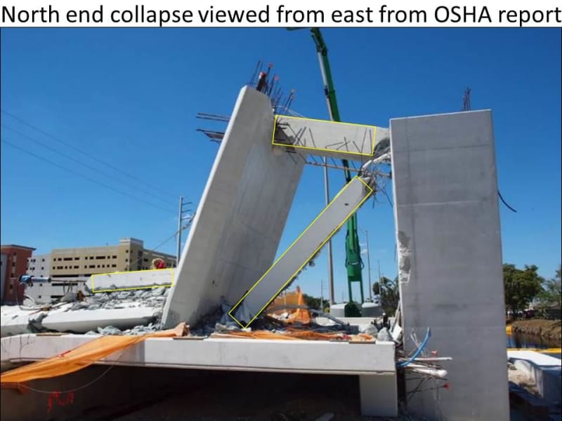
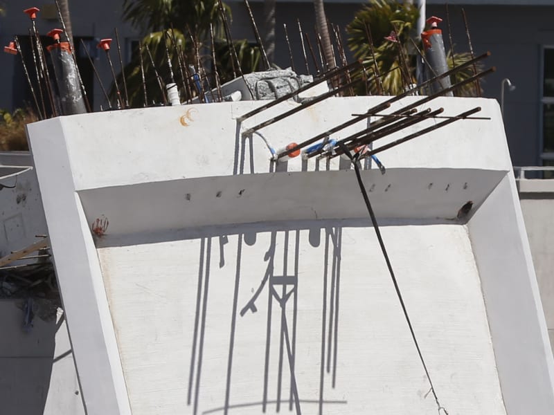
12_remains_muv8xu.jpg


Another view of #12
12_Crack_w3cvhw.jpg


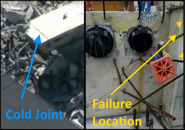
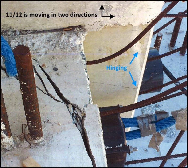
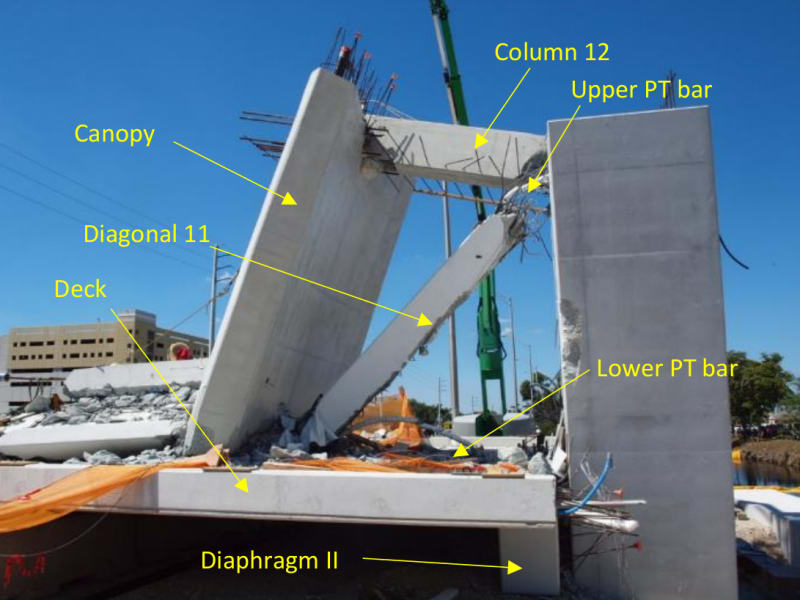
Following up on the last post by Sym P. le (Mechanical) - More and more it looks like the failure was purely the 11/12 anchor zone of the Upper PT bar. That the fractured mass of concrete & rebar in front of the anchor plate yielded. It is certainly true that prior to work, to retension the PT bars in #11, that all the rebar in the 11/12 node was resisting the weight of the bridge but when the front of the 11/12 node failed towards the south, #12 was momentarily relieved of performing any work other than self weight & the canopy.

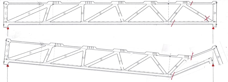
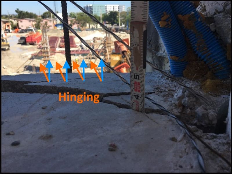
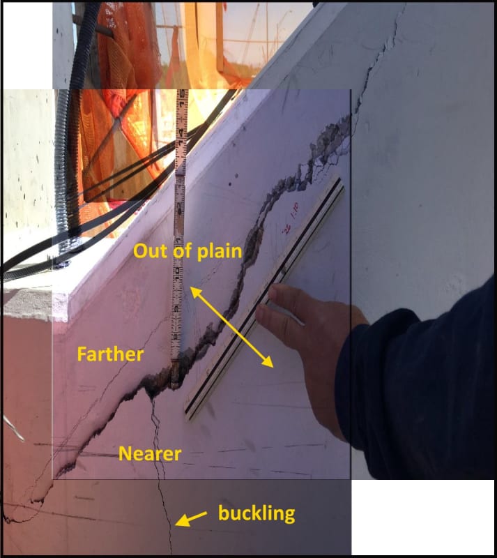
The base of 12 was already hinging upwards & outwards before the collapse. That is why their are cracks in the base of 12 before the collapse. Because it is bending at the deck/diaphragm elevation.

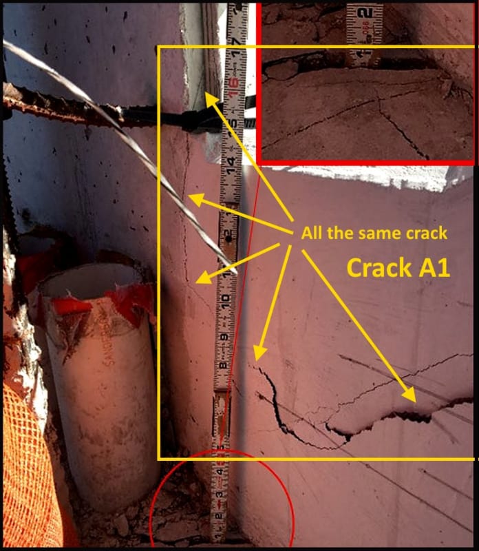
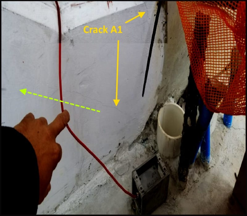
It is hard to perceive from the photos available but I think it is very likely, that the #11 upper PT bar and the concrete surrounding it, had failed completely during detensioning and that the only thing holding the bridge in place was Rebar & mechanical interlock of the broken pieces of concrete. That isn't to say that there wasn't progressive cracking but that the concrete was now little more that a pinned & caged rock formation, holding up a bridge. The more you group the cracks into a whole, the more it becomes clear #12 was lifted slightly during the initial cracking at the time of detensioning.

The deck and diaphragm haven't moved but the failed concrete still homogeneous to 12 has lifted. (Rotation)
11-12_hinging_ifxivj.jpg


11-12_hinge_zabrau.jpg


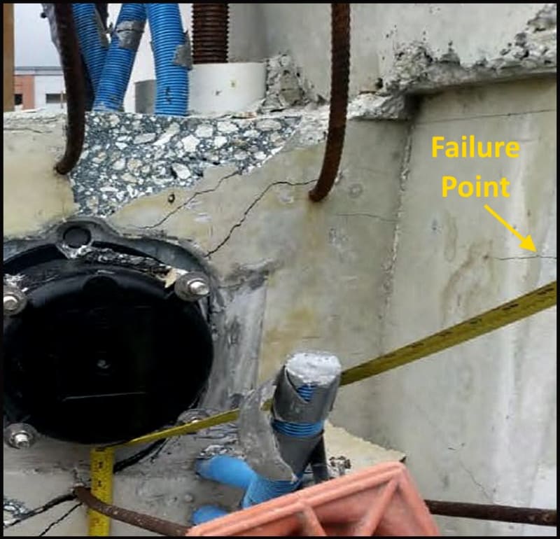
It appears more & more, to my my mind, that the front of the 11/12 node failed to the south.

Crack_in_11-12_loe9lf.jpg

Crack_A1_wmyedo.jpg


This kind of failure, if accurate, sort of raises the issue as to the procedure used to detension the PT bars. I've managed too many jobs to rule out and "Oh Crap!" moment. Most jobs have a number of them. It is just the nature of the people doing the work. You can give people all the training in the world but there are still instances, where if you don't spell it out for them, they revert to stupid. This is where I go back to Member 11.

cracked_11_dxc8om.jpg


Here in California, residential post-tensioned concrete has warning signs posted in the garage & stamped into the concrete at the point were the garage floor meets the driveway. It is just one example of the extreme hazards associated with Prestressed & Post-Tensioned concrete. The FIU Bridge plans & Structural Groups, VSL shop drawings are all loaded with Caution & Danger warnings. The work area hazard & safe zones for PT work are defined. Likewise the majority of Figg's work is Post-tensioning structure, including cantilevered segmental bridge work. Does anybody really believe that Post-Tensioning Institute or PCI would ever suggest that is was OKAY to tension a cracked concrete member? VSL should never have agreed to retension #11 and should have known better. Figg was just completely out of their minds. BPA was out of their depth but should have also understood that retensioning was a harebrained & dangerous idea. It begs the question whether firms offering Inspection services should be required to have one member that has been through some failure analysis course work, so that when things go sideways, they can step up.
 
Tomfh said:
.... Paint.net

Wow! I remember trying this out while this was still a student project by a kid at at Wazzu. VirtualDub was also a student project, and IrfanView was released when the author was 22 (as a DOS only program, if I remember), so I assume it was a class project as well. Smart kids!
 
epoxybot (Structural) 12 Jul 19 00:29 said:
The base of 12 was already hinging upwards & outwards before the collapse.

If the span was starting to sag at all, does this up-and-out lifting of 12 correspond to what I was trying to explain in my cut-and-paste mashup of 11 Jul 19 20:46, or is it just a coincidence? I'm not a structural guy, but once I figured out that concept the whole collapse video started making perfect sense to me.

ADD: Even without hinge points, it seems like the same pull-deck-south and push-canopy-north dynamic should hold true if the span sags, just on a much smaller scale.
 
MikeW7 said:
The north canopy section (and the upper section of member 12) was pushed north
I like your diagram and agree with your interpretation. I do note that the canopy/12 node was significantly crimped during the collapse before springing back. The damage can be seen on the canopy roof on the post collapse photos, not to mention the damage to 12 at the node. This would have been pushing on the top of 12 from the earliest stages and would participate in opening the vertical crack at the filet of 11/12.

Canopy_roof_cracks_nqjw65.jpg

12_Damage_hgi1wa.jpg

bridgecollapse.2_izxoyw.gif
 
epoxybot said:
VSL should never have agreed to retension #11 and should have known better. Figg was just completely out of their minds. BPA was out of their depth


I think we all agree it wasn't a wise move to retension!

But I can understand why experienced engineers and stressors would take that decision, even though with the benefit of hindsight it was clearly a bad decision.
 
Status
Not open for further replies.
Back
Top