Continue to Site

Eng-Tips is the largest engineering community on the Internet

Intelligent Work Forums for Engineering Professionals

  • Congratulations GregLocock on being selected by the Eng-Tips community for having the most helpful posts in the forums last week. Way to Go!

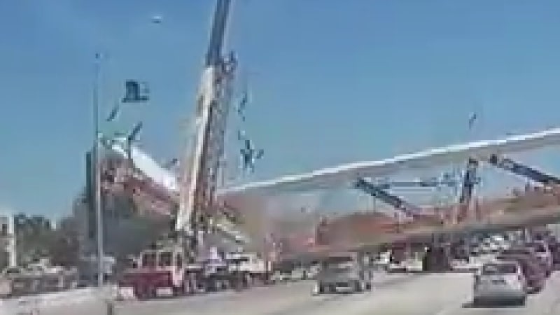
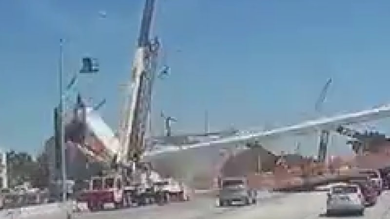
Miami Pedestrian Bridge, Part XI 32

Status
Not open for further replies.

JAE

Structural
Jun 27, 2000
15,463
A continuation of our discussion of this failure. Best to read the other threads first to avoid rehashing things already discussed.

Part I
thread815-436595

Part II
thread815-436699

Part III
thread815-436802

Part IV
thread815-436924

Part V
thread815-437029

Part VI
thread815-438451

Part VII
thread815-438966

Part VIII
thread815-440072

Part IX
thread815-451175

Part X
thread815-454618


Check out Eng-Tips Forum's Policies here:
faq731-376
 
Replies continue below

Recommended for you

Epoxybolt said:
Does anybody really believe that Post-Tensioning Institute or PCI would ever suggest that is was OKAY to tension a cracked concrete member?

Can be the correct thing to do depending on the circumstances.
 
Epoxybolt,

I don't think that the diagonal cracks in 11 and the vertical crack on the south side of #12 are the same as indicated in the note in the marked up photo. I think you are correct in stating that the base of 12 was rotating which caused the vertical crack on the south side of 12.

There was a large increase in vertical steel in 12 compared to the rest of the joint. The south three feet or so was sliding. The base of #12 was not going to move so easily. #11 is essentially pushing the bottom of #12 which is being resisted and anchored by the #12 vertical bars. This is why there is also some rotation. The base of 12 is firmly anchored so the chunk of concrete at the base of 12 starts to rotate outward.

#12 had 3#11 vertical bars on the south side and a total of 9#7 bars on the other faces. Those bars essentially stopped the chunk of concrete at the base of 12 from sliding.
 
I think I cover the concept of using PT in fractured conditions with Rock Anchors. None of it is done without some fairly well defined conditions of the substrate, which is absent in the FIU Bridge circumstance.

MikeW7 (Electrical) - I went back and watched the video. The South Diaphragm is pulled to the North during the collapse.
South_Diaphragm_hxjaho.jpg


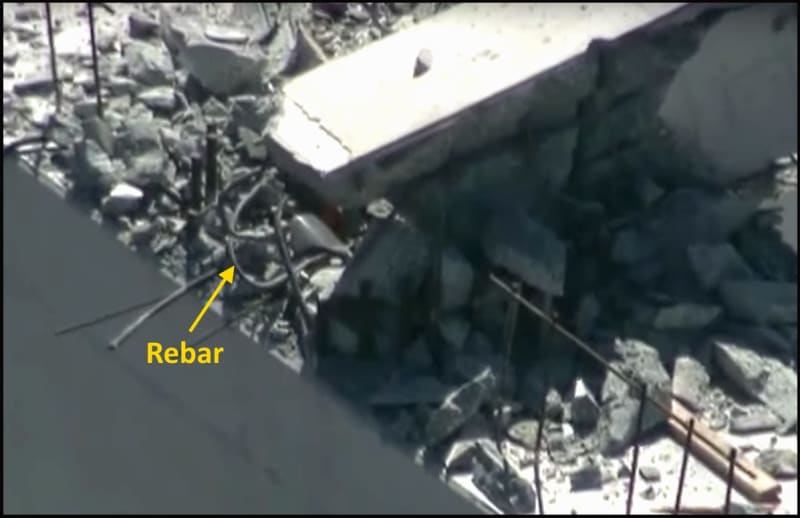
I think the tortured nature of the rebar in the base of 12 suggests that it momentarily stood independent of 11, dropped ~straight~ down and slid out the back of the north diaphragm, before being dragged back to the south by the diaphragm and the deck.

12_rebar_t7kfya.jpg


Ufo2_ht244o.jpg
 
Earth314159 (Structural) - I'm a bit confused by your 1st paragraph and photo references.

The 2nd paragraph agrees with my thinking. The concrete has failed and the rebar is ballooning out the back of 12 to the north and vertically. The rebar in the back of 12 is also more securely developed in the diaphragm.

 
Epoxybolt said:
The 2nd paragraph agrees with my thinking. The concrete has failed and the rebar is ballooning out the back of 12 to the north and vertically. The rebar in the back of 12 is also more securely developed in the diaphragm.

I speaking of the cracks prior to failure. It took more stress to move the base of #12 than the base of #11. Hence you get the vertical crack on the south side of 12 and rotation prior to the final failure.

I am not too sure which side of 12 is the "back" side. You mention "A1 crack" and the vertical crack as being the same crack. I am not too sure why you are doing that. The diagonal cracks in #11 are due to shear friction and the vertical crack in #12 is due to rotation at the base of 12.
 
epoxybot said:
The base of 12 was already hinging upwards & outwards before the collapse
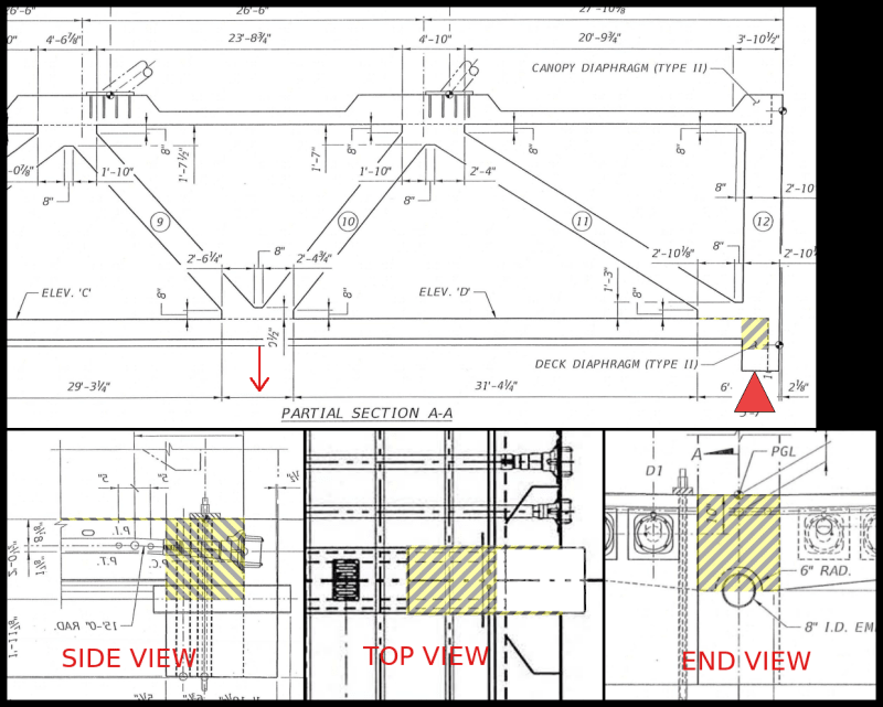
I'm not sure I follow the ascension theory. It's been raised before but I've always seen this as a descent into the depths... Seriously though, we don't have a solid baseline to reference the distortions and I think the engineers were at a disadvantage as a result. I also tend to believe that the 11/12 node cradled in the deck/diaphragm was largely intact. The surface flexure cracks could be picked up by the rebar. My idea of 11/12 snapping free was with regards to the surfaces as indicated in the following diagram or adjacent areas where 11/12 could easily be detached from the deck/diaphragm. Consider the chevron areas as gaps with no rebar and the deck lowered at the red ARROW as a quick example of the freedom of movement that would be allowed.

Consider_This_axagjp.png
 
Earth314159 (Structural) I reference (A1) as one singular crack formation that travels down the west vertical face of 11, then up and across the south vertical face, at the base of 12, that is, above & across the 11/12 node/fillet and then up the east vertical face of 11. The backside of 12 being the northerly face.

I refer to failure (Concrete) as something that has taken place prior to collapse.

I'll try and explain myself further tomorrow.
 
epoxybot (Structural) 12 Jul 19 02:26 said:
The South Diaphragm is pulled to the North during the collapse.

As the 1-10 truss section begins to fall it appears to mostly just tilt at the pivot point formed by the south pier bearing pads. The south diaphragm isn't significantly pulled north until the deck hinge hits the pavement and the 1-10 truss flattens out.

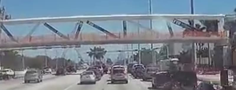
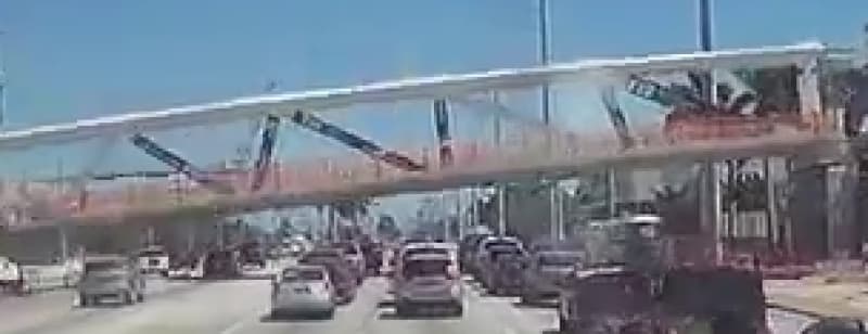
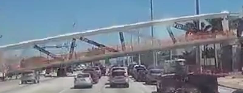
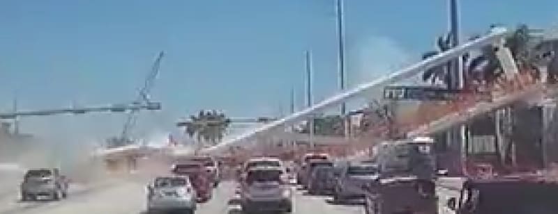
From the dash cam video: ZIP file of cropped frames 074-088 and AVI video of the south end, all "enlarged" with nearest neighbor algorithm (each pixel replaced by 4x4 block of identical pixels) to minimize artifacts.

Relevant frames 076, 080, 081 and 087:

South end - Frame076
Frame076_p9al0y.jpg


South end - Frame080
Frame080_mieyu4.jpg


South end - Frame081
Frame081_ngth0x.jpg


South end - Frame087
Frame087_yfhyir.jpg


Meanwhile at the north end, when the deck hinge hits the pavement at Frame081, the north diaphragm is almost completely off its pier and member 12 has fallen behind the pier. A fifth of a second later, at Frame082, the north diaphragm is off its pier:

North end - Frame081
Frame0081_fxrjyn.jpg


North end - Frame082
Frame0082_gcxgqr.jpg


Note that in Frame082, the "falling man" is still in the air. What an incredibly fast sequence of events....
 
MikeW7 said:
What an incredibly fast sequence of events....
It sure is. The most important piece providing support had signaled for days that it was in trouble.
One of the Prime Directives for designing Reinforced Concrete is to NOT over-reinforce it. The codes provide limits to the amount of reinforcing which can be used. Specifically, to ensure the steel fails before the concrete fails. The reason ? Steel has a long yield curve and can stretch while yielding but retain strength until failure, and therefore undergo a lot of strain. Which usually translates to deflections and cracking and somebody being alerted to a problem.
Not so with concrete - concrete fails abruptly. But it does not disappear - so a column can be highly loaded and still provide support - IF the concrete remains confined with steel ties well detailed. Such a structure in this condition will need serious repairs or even demolition, but it may not fall abruptly.
Taking advantage of the time provided can save lives.
Great work with the images.
 
MikeW7 said:
Note that in Frame082, the "falling man" is still in the air. What an incredibly fast sequence of events....

The workers were attached to a line strung center-line across the 174 foot canopy. This worker was held aloft either by being entangled with something during collapse or because he intentionally attached his harness to crane cable at some point. In any case your image is just after his harness failed. Read OSHA citation for that violation (Sep 9 2018, pages 6-7):
 
The falling guy - take a yardstick, set one end on a support and hold the other level. Put a coin onto the held end and then let the yardstick go. The coin will fall more slowly than the end of the yardstick.
 
jrs_87 (Mechanical) 12 Jul 19 22:00 - The canopy first deflected in frame 077, and the deck hinge point hit the pavement at frame 81, 0.8 seconds later. The falling man didn't have his crotch straps buckled and the only resistance his harness offered was the time it took to yank his arms up to allow him to drop out. His feet were never more than 2-3 feet above the canopy all the way down. What an incredibly fast sequence of events....
 
Not sure how the harness could see any resistance. The safety cable was attached between the two ends of the canopy which were coming together and a fast pace; the cable would have gone slack almost instantly.
 
3DDave said:
The falling guy - take a yardstick, set one end on a support and hold the other level. Put a coin onto the held end and then let the yardstick go. The coin will fall more slowly than the end of the yardstick.

It is counter intuitive but true. The south bridge support adds a rotation force (a couple between the CG and the south support) that allow the tip of the yard stick or north end of the "remaining bridge" (for lack of a better description of the south portion of the bridge) to accelerate faster than G. The CG of the remaining bridge is accelerating slower than G but the north end of the remaining bridge is accelerating faster than G.
 
3DDave (Aerospace) 13 Jul 19 01:57 said:
Not sure how the harness could see any resistance.

He had his lanyard attached to the crane lifting hook, so he's probably part of the mobile crane crew that positioned the jack equipment for VSL. See the images posted by saikee119 (Structural)8 Jul 19 16:38 - he's yanked up in frames 78-79 as the canopy drops out from under him, then falls out of his harness (with his arms over his head) in frame 80. After that he's in free fall and stays within a couple of feet of the canopy. Frames were taken every 0.2 seconds (5 fps).

Midsection of the canopy was 12.5 feet wide with a raised lip on each side, so it's no surprise he had his crotch straps undone. That's like a basketball court for guys used to working at elevated heights. I know because I was one of them - drove a mill crane and worked with millwrights and iron workers...

EDIT ADD: I think the six people on the bridge were part of different crews, so each crew may have had their own safety protocals.
 
JRS 87 said:
Read OSHA citation for that violation (Sep 9 2018, pages 6-7):

The citation appears to say that the worker was attached to the horizontal life line in top of the canopy. I don't think that the citation is necessarily issued for contributing to injuries. It was just that proper safety protocol was not followed.
 
EDIT: added more info and details on citations

OSHA cited five companies for fall protection violations. I check up on this from time to time to see if the violations are ever closed. The two other companies at the end aren't part of the FIU inspection - they got intertwined with the search somehow.
[ul]
[li]Details for the specific citation to Structural Technologies are in the PDF document cited by jrs_87 (Mechanical)12 Jul 19 22:00[/li]
[li]Basic information about the two citations (01001 and 01002) mentioned in the link above are as follows:[/li]
[/ul]
Citation 01001 refers to Standard 5A0001 OSH Act General Duty Paragraph:
(a) Each employer --
(1) shall furnish to each of his employees employment and a place of employment which are free from recognized hazards that are causing or are likely to cause death or serious physical harm to his employees;
(2) shall comply with occupational safety and health standards promulgated under this Act.​
(b) Each employee shall comply with occupational safety and health standards and all rules, regulations, and orders issued pursuant to this Act which are applicable to his own actions and conduct.

Citation 01002 refers to Standard 1926.502(d)(16)(iii)
[ul]
[li]1926.502 - Fall protection systems criteria and practices.[/li]
[li](d) - "Personal fall arrest systems." Personal fall arrest systems and their use shall comply with the provisions set forth below. Effective January 1, 1998, body belts are not acceptable as part of a personal fall arrest system. Note: The use of a body belt in a positioning device system is acceptable and is regulated under paragraph (e) of this section.[/li]
[li](16) - Personal fall arrest systems, when stopping a fall, shall:[/li]
[li](iii) - be rigged such that an employee can neither free fall more than 6 feet (1.8 m), nor contact any lower level;[/li]
[/ul]
 
Has anybody noticed the jbar in the youtube video > FIU Bridge Collapse Lift off of 12 explains J-bar pristine condition < does not match up to the drawing?
Fig 63 in the OSHA report does lead you to believe jbar was not embedded into deck.
In fact by the pics the jbar (in pristine condition) appears to have been bent to fit the deck after pour and cure.
It's bent to fit and 180 degrees out from the print.
It was supposed to be right next to lower rebar embedded in concrete.
Fig 63 certainly shows it was not.
It's pristine alright and tells a tale.
Keep comparing fig 63 and the video jbar pic and the print.
Just a little detail.
It's just amazing how such a small rebar can go thru all that destruction and come out unscathed........
just how is that possible?
 
RAB678 said:
It's just amazing how such a small rebar can go thru all that destruction and come out unscathed........
just how is that possible?

I commented on the J-bar in Part X 21 Jun 19 23:22. I came to the same conclusion that the rebar was not in accordance with the drawing.

As far as how the rebar can be unscathed, check my comments in this thread 29 Jun 19 17:27, 11 Jul 19 19:23. In the second I propose that an impluse extending from a smaller initial sudden failure shattered the lower end of 11. I'm interested in hearing others thoughts on this.
 
Status
Not open for further replies.

Part and Inventory Search

Sponsor