Continue to Site

Eng-Tips is the largest engineering community on the Internet

Intelligent Work Forums for Engineering Professionals

  • Congratulations KootK on being selected by the Eng-Tips community for having the most helpful posts in the forums last week. Way to Go!

Miami Pedestrian Bridge, Part XII 34

Status
Not open for further replies.

zeusfaber

Military
May 26, 2003
2,466
A continuation of our discussion of this failure. Best to read the other threads first to avoid rehashing things already discussed.

Part I
thread815-436595: Miami Pedestrian Bridge, Part I

Part II
thread815-436699: Miami Pedestrian Bridge, Part II

Part III
thread815-436802: Miami Pedestrian Bridge, Part III

Part IV
thread815-436924: Miami Pedestrian Bridge, Part IV

Part V
thread815-437029: Miami Pedestrian Bridge, Part V

Part VI
thread815-438451: Miami Pedestrian Bridge, Part VI

Part VII
thread815-438966: Miami Pedestrian Bridge, Part VII

Part VIII
thread815-440072: Miami Pedestrian Bridge, Part VIII

Part IX
thread815-451175: Miami Pedestrian Bridge, Part IX

Part X
thread815-454618: Miami Pedestrian Bridge, Part X

Part XI
thread815-454998: Miami Pedestrian Bridge, Part XI

Check out Eng-Tips Forum's Policies here:
FAQ731-376: Eng-Tips.com Forum Policies
 
Replies continue below

Recommended for you

hokie66 (Structural)12 Aug 19 00:55
The Mad Spaniard,

So by your comments, I take it that you believe the rest of the bridge was just fine, and that the only problem was at the joint which failed first. That is a big assumption, but one which seems to be common in the recent discussions here


Greetings:

Very soon this is going to be the most analyzed structure ever. We have already three FEM analysis: FIGG, BERGER and OSHA. THe NTSB is going to analize big time. I am sure that there are at least more than a couple of Master students out there in the world using this bridge to get a degree.

So, we are going to have several papers/documents showing forces in he existing structure and telling us what when wrong and where.

I believe that the connections strut/deck or strut/canopy show "little meat and bones" . I will put a little more concrete and steel there to beef-up them up and avoid "nasy cracks" that would create "masty paperwork and media attention" (We all in Florida remmember the construction of Shyway).I even would use fiber reinforcing concrete there and in the struts. And definitly, I will add some internal details to retrofit the connection #11/deck. But from practical and visual purposes the connections will be the same for a non-engineer.

Best reagrds
 
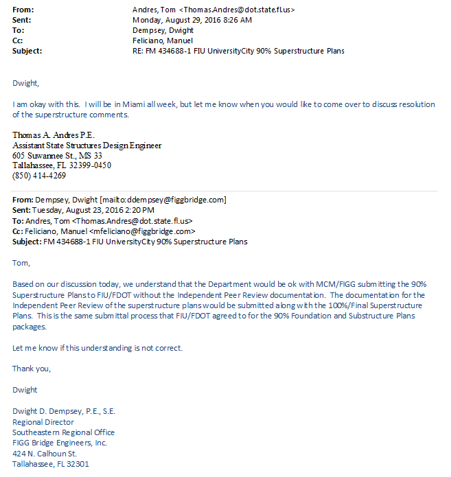
FDOT & FIGG email regarding 100% Plans PEER Review. The NBC Timeline is quite handy.

8-23-16_email_and_response_glmjb7.png


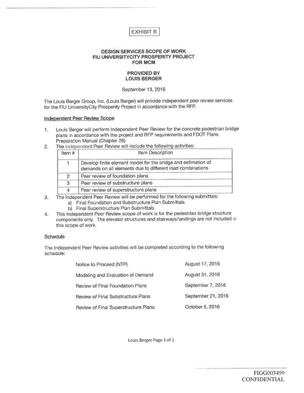
Scope of Work
FIGG-Louis-Berger-Agreement-p9-normal_mj41wm.gif
 
epoxybolt said:
FDOT & FIGG email regarding 100% Plans PEER Review. The NBC Timeline is quite handy.

That looks like a typical communication. Everyone one wants to get their foot in the door for permit approvals so the last thing to get submitted is the independent review documents. You have to be close to finishing the design drawings before the independent review is completed. At least now we know the drawings would have been close to finished for the review.
 
I didn't see anything there that prevented Berger from examining the whole construction scheme, including the main span standing alone. The scope required them to review the whole bridge, but not before the documents were complete. OSHA may have misinterpreted, or been misinformed, about reviewing construction stages as opposed to design stages. The main thrust of OSHA's report is that the road below should have been closed, and no one now should argue with that.
 
Peer Review by Berger
From the schedule proposed by Berger we learn they intended to spend 7 weeks on the peer review. That is 35 working days and for a $61,000 fee that is $217 per hour.
The Berger scope includes the following:
3. The Independent Peer Review will be performed for the following submittals:
b) Final superstructure plan Submittals​
An hour spent studying the plans would have revealed to an engineer that the 174 foot span was required to span and support its own weight and construction loads for a period of time, until the back span was complete and cured.

I have no experience in performing FEA analysis - how much time could it have taken to remove the back span and everything except the bare 174 foot section from the model and run the 174 foot section independently with dead load and construction loads?

The ABC idea imposes different conditions than typical in-place construction - (all here understand that). In non ABC construction, the contractor is responsible for everything - falsework, materials, jobsite safety, procedures, public safety (with approval by the agencies) - the contractor "owns" the thing until it is complete and accepted by the Owner and authorities. The design of any portion subject to ABC procedures would be the responsibility of the design firm. FIGG's drawings show the steps for the ABC process in this project.

It appears that everyone thought if the finished structure works it will work at every step in the process.
But were the ABC requirements of this project not addressed clearly on the "Superstructure Plans"?
I think we would find the emails between Berger and FIGG very interesting.

 
I've asked this a couple times, and I don't believe that there has yet been posted a satisfactory answer:

What are the substantive structural differences between the as-collapsed construction stage and the final stage, and how would they have prevented collapse?

Clearly the final stage would have included the back span, the pylon, and its decorative faux "stays" that make it look like a cable-stayed bridge. But I have yet to see a convincing case that these elements would have substantially increased the capacity of the structure.

The back span's 13/14 node would probably have buttressed the 11/12 node and increased its resistance to getting pushed off the deck by the horizontal component of the compression force in 11. But there does not appear to have been any provision to structurally tie together the decks of the main and back spans. So it seems to me that the back span would have just changed the failure mode so that what happens is that the horizontal component of the force in 11 just pushes one or both decks off of their piers with basically the same result. It might have taken a bit more live load to make that happen, but that might have been a blessing in disguise: The live load could well have been in the form of a spring break party consisting of hundreds of students.

Thoughts?

--Bob K.
 
Good question, Bob K. My examination of the drawings was only cursory, but it seemed to me that the connection between the two spans was only nominal, perhaps for lateral stability. To make the bridge truly continuous over that support would have required much more robustness, and the top chord might have been deficient in tension. As well, the diagonals at the support would have taken even more load than in the simple span condition.
 
They’re simple spans aren’t they?

Why would it be a continuous bridge if they’re dropping the spans in one at a time?
 
I hope someone will answer Bob hpaircraft's question. Since 11, the canopy, and deck all failed without 12 moving, I don't see what the pylon and back span would have contributed to preventing the failure? Wouldn't the weight of the faux cables, expanding on a hot day, have only contributed to the load on 11? How the failed 11, canopy, and deck would have fallen, is a different question that I'm not prepared to hypothesize on.

SF Charlie
Eng-Tips.com Forum Policies
 
Tomfh said:
They’re simple spans aren’t they?

Why would it be a continuous bridge if they’re dropping the spans in one at a time?

There is bending continuity at the support. C1 and C4 cables run through for a factored tensile force of 2500 Kips in the canopy at the pier location. That is quite significant. This cannot be analyzed like a typical continuous span. The staging makes a big difference to the loads. The hogging moment can also be fine tuned unlike other typical continuous spans.
 
hpaircraft said:
I've asked this a couple times, and I don't believe that there has yet been posted a satisfactory answer:

What are the substantive structural differences between the as-collapsed construction stage and the final stage, and how would they have prevented collapse?

Clearly the final stage would have included the back span, the pylon, and its decorative faux "stays" that make it look like a cable-stayed bridge. But I have yet to see a convincing case that these elements would have substantially increased the capacity of the structure.

I have partially answered this before. As you allude #11 and #14 buttress each other off. Now, only the difference in horizontal shear has to go through the pour joint. This substantially reduces the shear friction stress for this one joint. The forces actually go up in #14 and #11 when the C1 and C4 cables (the C1 and C4 cables are continuous over the pier and connect the canopies on the two sides together) are pre-stressed but the load transfer is still less.

There were still other issues with the design. You could argue that the tube stays would help but they were supposed to have been ignored for the strength. The tube stays would actually increase the shear loads on the joints if there was so much PT in the deck that caused an upward cambre. As concrete creeps, the camber can actually creep up. The deck may also creep down in which case the tube stays help relieve the stresses in the concrete joints.

There were also other failure mechanisms in the joints what would not have been resolved by having continuity in the spans such punching in the deck. The tie arrangements in the diagonals do not meet code (I am assuming the US code is similar to other codes in this respect). There is no easy fix to this issue.

Even if Louis Berger only reviewed the final stage, there were still many issues that they should have identified. To be fair, they may have identified all the pertinent issues for the final stage. It could be that the issues were never properly addressed in the final drawings.
 
ABC is similar in other prestressed structures. You may have ABC without prestressing or you may have prestressing without the ABC processes. If either one or both of these conditions apply, you have to review multiple stages. Prestressing behaves differently in the construction phase, short term and the long term. The loading conditions are also different in the long and short terms.

In the construction phase, the concrete is weaker and less stiff. The initial prestressing can over load the top of a beam (or truss in this case) in tension (near the ends of the span). Young's modulus is effectively different in the long term and short term (a factor of 2.5 to over 3 in stiffness). For short term and infrequent loads, you may choose to use the short term young's modulus. For dead weight and prestressing, you need to use the long term young's modulus for long term results. This all implies that you need multiple models for the different load combinations. The forces on the stays are affected by both longer term and short duration loading conditions.
 
It is not clear to me how the PT in the canopy would transfer any weight off 11. I did not see any mechanism to tighten the faux stays. 11 doesn't seem to have needed 12 to move for 11 to fail. 11 seems to become visibly shorter early in the collapse.

SF Charlie
Eng-Tips.com Forum Policies
 
SFCharlie said:
It is not clear to me how the PT in the canopy would transfer any weight off 11. I did not see any mechanism to tighten the faux stays. 11 doesn't seem to have needed 12 to move for 11 to fail. 11 seems to become visibly shorter early in the collapse.

The PT in the canopy actually increases the load on #11 and does not transfer any weight off of 11. #11 and #14 counterbalance each other so the shear at the pour joint can be reduced. The shear is the difference between the horizontal components of the two loads.

There is no mechanism to tighten the stays. Sag (if it sags) in the deck would load the stays in tension. Cambre in the deck would compress the stays and increase the loads (or a hot day as you noted above) on the truss.

11 would have to fail in compression if 12 was immovable with infinite attachment strength to the diaphragm or the joint up at the canopy would have to fail (likely the next weakest link in the load path).

There is shortening in 11 (you can't avoid compression strains)but mainly what you see is sliding and not shortening.
 
C-1 and C-4 PT effects
Help me here - From drawing B-69 I see 2 X C-1 tendons at 430 kips = 860 kips and 2 X C-4 tendons at 863 kips = 926 kips for a total delayed PT force of 1786 kips actual force.
A free body of each span about the pylon would appear to be a 1786 kip force 16 feet above the deck at each end, with the north and south ends on low friction bearing pads, unrestrained. Would that not create a moment at the pylon of 1786k X 16 feet = 28,576 ft-kips? That lifts the south end by 28,576/174=164 kips added to the reaction at the pylon. Likewise for the back span, that moment adds 298 kips reaction at the pylon.
Of course this is at a completed stage for the project. But of importance here is that it adds 164 kips vertical component to the force in member 11. That adds 311 kips axial compression to member 11 (unfactored).
In reviewing the strut reinforcing, I see member 9 has 10 -#7 bars while member 11 has 8-#7. Member 11 has much more load than member 9.
From drawing B-39 and 40 Member 9 is section A=A " Member with no PT bars" has 10 bars. Elevation of member 11 on B-40 calls for 2 bars each face for a total of 8. But member 11 has the PT bars for lifting and transportation. This looks like a failure to coordinate a condition that changed when the transporters were relocated and the PT was added to members 2 and 11.
I don't know if 10 bars could have saved it or not but 11 was splitting badly before it collapsed.
 
Earth314159 said:
...The forces actually go up in #14 and #11 when the C1 and C4 cables (the C1 and C4 cables are continuous over the pier and connect the canopies on the two sides together) are pre-stressed but the load transfer is still less...

Interesting. Yes, I can see how connecting the C1 and C4 tendons might have helped prevent the failure we saw. But I think that connecting the two decks as well would have been much better. From the tone of the Figg correspondence about "capturing the node," I would bet that they might have been hatching a plan to do just that, using the same connection scheme that they were planning to use to join the PT tendons in the canopies of the span and backspan. As I've written before, maybe they could have used the same coupler nuts that would have prevented the Hyatt skywalk collapse. But at this point we'll probably never know for sure.

--Bob K.
 
I must agree - many questions remain. Your concerns point out the complexity of this project. You have covered most of the pertinent points. I originally challenged the concept that when finished all will be well, but now I see the next stage could have helped - but the extent is questionable. The pylon section to be cast thru the truss and wrapping 12 and 13 could have helped tie the sections together. It would need many ties and much reinforcing across a finished construction joint and into the deck surface, and I see little provision for this on the drawings. The idea to add late PT in the canopy could well serve if applied to the deck PT and provided a clamping force over the pylon at the deck level. How well the late PT force in the canopy transfers thru the webs to the deck is problematic, I think. Shear lag comes to mind. In a simple free body diagram it seems to work.

The connection over the pylon appears problematic. But with members 11 and 13 opposing each other thrust wise, the net force between the superstructure and the pylon is reduced - IF the two sections are well connected together. The expansion joint at the south bent is 2". That could limit the slip IF there were adequate resistance provided by the south stairs. But the bottom of 11 had slipped less than 2" when the collapse began.

I have previously expressed those same thoughts. Sadly, the early collapse may have been the best way out. That is a poor and regrettable comment for a project.
 
Seismic Connection to PYLON
The completed superstructure is connected to the Pylon but has slip bearings at the south and north ends. The ends have no provision for restraint in the east-west or north-south direction.

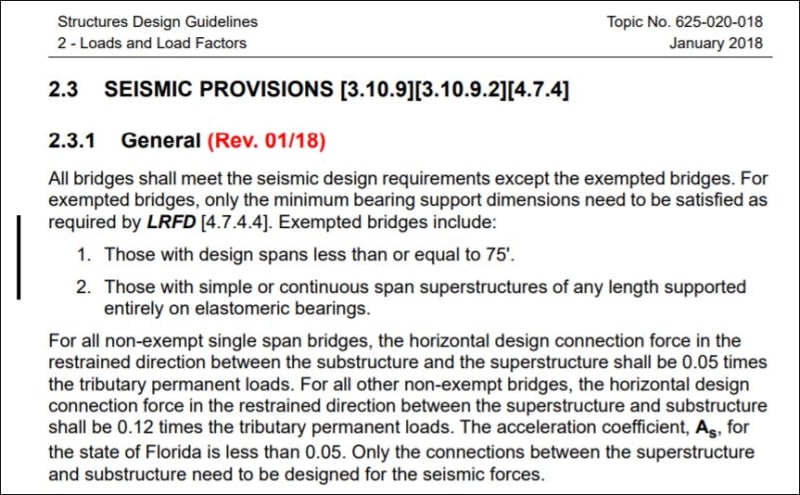
FDOT section on Seismic:
FDOT_Seismic_g0e544.jpg

The completed structure is a two span bridge and for seismic loads the entire superstructure is tributary to the pylon. As I read that, the connection of the superstructure to the pylon would be 0.12 X (950 tons X 270'/174') = 177 tons or 353 kips. That seems to be adequately resisted if the member 11 and 14 loads are otherwise accounted for.
The superstructure itself is exempt from seismic design. I presume the pylon and substructure would be designed for this horizontal force.
 
Vance Wiley said:
C-1 and C-4 PT effects
Help me here - From drawing B-69 I see 2 X C-1 tendons at 430 kips = 860 kips and 2 X C-4 tendons at 863 kips = 926 kips for a total delayed PT force of 1786 kips actual force.

That is the correct idea. You should also add in the live loads. I don't have my work books, spread sheets, or favorite calculator at home but here is a quick approximation of the diagonal #11 factored loads and squash capacity (no slenderness taken into account). I will assume a tension capacity of 2500 Kips for C1 and C4. The conduits are grouted so I think this is fair but it may be a little conservative since I may not need the full 2500 Kips. I am going off memory for the capacity equations (the US equations may also vary a bit). I usually use the interaction diagrams for the axial and bending squash load capacities. The longitudinal bars are just barely 1% of the cross sectional area which is just enough where the code allows you to take the full concrete section into account. The tie arrangement does not meet code requirements which I am ignoring. I usually calculate capacities in metric and use metric sized rebar so if I made an error, let me know.

Reaction: 1.25x950Kips+1.5x30'x175'/2x90psf/1000+2500Kip*16'/175'=1190+350+230=1770 Kips
Load from #12 and end span of deck/canopy: 1.25*8kip/ft*15'+1.5*15'x30'*90psf/1000+1.25*3kip/ft*12.5'+1.25*2.9'x1.75'*14'*150/1000=150+60+47+13=270Kips
Net vertical component into #11: 1770-270=1500Kips
Total load in #11: 1500/sin(32)=2830Kips

Capacity of column: 0.8*0.65*8.5ksi*24*21+8*30.6Kips=2230+245=2475Kips<2830Kips therefor NG.

If you ignore the increase in the load due to the hogging moment, the #11 compression load reduces to 2400Kips. This only gives 75 Kips (40 Kips reaction) to play with. C1 and C4 can only be tightened to 430 Kips until the diagonal #11 is overloaded by code in compression. It is still not a likely point of failure but it doesn't meet code requirements.

In any case, it appears that the design for #11 in compression is insufficient for the full gravity load case. The tie arrangements also do not provide sufficient confinement for the concrete core of the column.
 
Status
Not open for further replies.

Part and Inventory Search

Sponsor